Introduction to Diaphragm design.

1-Diaphragms:
Diaphragms is a horizontal or sloped system acting to transmit lateral forces to vertical elements of the lateral force-resisting system (LFRS). Generally provided by the floor and roof systems of the building; sometimes, however, horizontal bracing systems independent of the roof or floor structure serve as diaphragms.
There are many types of materials and systems for use as floor and roof diaphragms.
Such as; Concrete slabs, Precast concrete floor planks with concrete topping, Metal decking with concrete fill, Roof sheathing .. etc.

2- Diaphragms roles for the structure, the main purpose of the diaphragm is to distribute lateral forces to the elements of the LFRS also it is doing the following:
1- Resist gravity loads.
2-Provide lateral Support to vertical elements.
3-Transfer lateral inertial forces to vertical elements of the seismic force-resisting system.
4- Transfer forces through the diaphragm.
The Largest diaphragm transfer forces should be anticipated at offsets or discontinuities of the vertical elements of the seismic-force-resisting system such as.
(a) Setback in the building profile
(b) Podium level at grade.
3- Diaphragms components:
A-Chord:
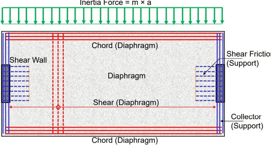
Is assumed to resist all the flexural tension from the diaphragm in-plane bending moment resulting from the lateral load. In case the edge beam is not existed the slab will act as a deep beam to resist flexural tension force and the chord tension reinforcement to be placed within h/4 of the tension face, where h is the diaphragm width in the direction of the analysis (section 12.5.2.3 of ACI code).
B-Collector:

Also called drag struts or ties, are diaphragm framing members that collect diaphragm shear forces from laterally unsupported areas to vertical resisting elements. The collector width can be fit within the shear wall width but in some cases, it has to be wider.
SEAOC 2005 recommends the collector effective width beff to not exceed the wall width plus a width on either side of the wall equal to half the contact length between the diaphragm and the wall.
4- Behavior of Diaphragms
The behavior of a diaphragm can be as beam that is supported springing which represents the lateral stiffness of lateral resisting elements. The floor or roof system acts as the beam web which resists the design shear force the chords behave as flange elements resisting the axial tension or compression resulting from flexural behavior.
5-Type of diaphragms:
Diaphragms are typically classified into three categories: rigid, flexible and semi-rigid
a- Rigid diaphragms

ASCE7-10 ( section 12.3.1.2) permits the assumption of rigid if the diaphragms aspect ratio is 3 or less for seismic and 2 or less for wind load ( section 27.5.4 of ASCE7-10) if the structure has no significant horizontal irregularities. The seismic story shear is to be distributed to the vertical elements of the LFRS based on the relative lateral stiffness of those elements.
b-Flexible:

Diaphragms is permitted to be flexible when the computed maximum in-plane deflection of the diaphragm under lateral load is more than two times the average story drift of adjoining vertical elements of the seismic force-resisting system of the associated story under equivalent tributary lateral load as shown in the above Fig. 12.3-1.
The seismic story shear is to be distributed to the vertical elements of the LFRS based on the tributary area. And the diaphragm deflection is significantly high compare to LFRS
c- Semi-rigid diaphragms simulate actual in-plane stiffness properties and behavior. it should be modeled when significant in-plane deformation does occur, or when required by code.
6- Code requirements:
The seismic design of the diaphragm is required for all buildings in SDC B to F.
ASCE7-10 12.10 required diaphragms to be designed for the internal forces determined as the maximum of :
a-

b-

The detailing of diaphragms is generally independent of the type of LFRS for building, therefore, the R-value does not appear in the upper and lower limit equation.
Section 18.12 of ACI 318-14 shall only apply for diaphragm design in building assigned to SDC D to F only. while chapter 12 of ACI318-14 provisions shall be applied and for buildings assigned to SDC B and C.
7- Diaphragm modeling and analysis approaches
The internal force in diaphragm can be calculated from hand calculation till complex computer analysis depending on the building's irregularity.
The following methods can be used for analysis:
1- Equivalent beam model.
2- Equivalent beam on spring model.
3- Corrected equivalent beam model.
4- Strut and tie model.
5- Finite element model.
8-How to obtain the diaphragm in ETAB.
The diaphragm forces can be obtained through sections cut as illustrated in the following link: https://wiki.csiamerica.com/display/etabs/Diaphragm+forces
Bear in mind the Stiffness modifiers for RC diaphragms commonly fall in the range of 0.15 to 0.50 when analyzing the building for design-level earthquake demands (Nakaki, 2000).
References.
1. Building code requirements for structural concrete (ACI 318-14) and commentary.
2. Minimum design loads for buildings and other structures (ASCE 7-10)
3. NEHRP Seismic Design Technical Brief No. 3.
Thanks to
https://core-en.com/blogs
Er. SP. ASWINPALANIAPPAN., M.E., (Strut/.,)., (Ph.D.,)
Structural Engineer
No comments:
Post a Comment