Thursday 3 September 2020

The evolution of composite flooring systems: applications, testing, modeling and Eurocode design approaches

 The evolution of composite flooring systems: applications, testing,
modeling and Eurocode design approaches


Steel–Concrete Composite (SCC) structural systems are increasingly used in the construction industry and becoming the subject of intensive research by the world's leading universities and companies because of their efficient material usage. This review paper summarises some historic and recent developments as well as the new trends for SCC systems. 

It presents the design philosophy and specific definitions for basic structural elements, including composite beams and slabs with emphasis on the applications, static tests, modeling techniques, design approaches as well as current design limitations. 

This paper concludes with a call for more research for the improvement of Eurocode 4, which in turn can help the fast-growing construction industry to take full advantage of the benefits of composite construction techniques implemented with safety.


© 2019 The Authors. Published by Elsevier Ltd. This is an open-access article under the CC BY license


(http://creativecommons.org/licenses/by/4.0/).


Thanks to 

Elsevier


Authors

Inas Mahmood Ahmed, Konstantinos Daniel Tsavdaridis ⁎


Er.SP.ASWINPALANIAPPAN., M.E.,(Strut/.,)
Structural Engineer


Experimental investigation of long-span cold-formed steel double-channel portal frames


Experimental investigation of long-span cold-formed steel double-channel portal frames


Highlights

Full-scale experiments on a series of long-span cold-formed steel portal frames

Failure due to column global buckling initiated at the knee brace connection.

Connection design greatly affects overall frame strength and stiffness.

Column base in-plane rotational stiffness was quantified.

Abstract

Cold-formed steel haunched portal frames are popular structures in industrial and housing applications. They are mostly used as sheds, garages, and shelters, and are common in rural areas. Cold-formed steel portal frames with spans of up to 30 m (100 ft) are now being constructed in Australia. As these large structures are fairly new to the market, there is limited data on their behavior and design recommendations. An experimental program was carried out on a series of portal frame systems composed of back-to-back lipped channels for the columns, rafters, and knee braces. The system consisted of three frames connected in parallel with purlins to simulate a free-standing structure, with a span of 14 m (46 ft), a column height of 5.3 m (17 ft), and an apex height of 7 m (23 ft). Several configurations were tested including variations in the knee connection, sleeve stiffeners in the columns and rafters, and loading of either gravity only or combined horizontal and gravity loads. Deflections were recorded at various locations to measure global and local movements of the structural members. A total of eight frames with unbraced columns were tested and one frame with braced columns. Experimental results are presented herein including frame strengths and failure modes for the various frame configurations and loading conditions, as well as quantified moment-rotation relations for the column base connection. The contributions and effects of the different knee connections and sleeve stiffeners are presented. The overall frame behavior of these structures and suggested design considerations are discussed.


Keywords

Cold-formed steel
Steel portal frames
Thin-walled structures
Experimental methods


Thanks to 

ScienceDirect


Author links open overlay panelH.B.Blu   & K.J.R.Rasmussen


Er.SP.ASWINPALANIAPPAN., M.E.,(Strut/.,)
Structural Engineer

Tuesday 1 September 2020

Tips for Design of RCC Concrete Beams


Tips for Design of RCC Concrete Beams


If you are new to the design of RCC Concrete beams or any structural members you might find it difficult because what we learn from books during civil engineering studies is different from what is practiced in the construction field. You shouldn’t worry “that” much because both analyzing and designing of structural members is easy once you understand industrial practices and get some experience. Here I am going to give a few tips for the design of RCC Concrete Beams.

Tips for Design of Size, Shape, and Span of RCC Beams

  1. Keep the width of the beam minimum. Some commonly used beam widths are 200, 230, and 300 for practical, structural, and aesthetic reasons.
  2. For plinth, beams assume overall depth from span/15 to span/18
  3. For Tie, beams assume overall depth from span/18 to span/20
  4. For Floor, beams assume overall depth from span/12 to span/15
  5. Design RCC Concrete beam section based on the maximum moment and shear force.
  6. Mu/bd^2 can go up to 6 in case of the heavy beam with long span
Epoxy coating steel bar tar based brush type epoxy coating
Pic:- Amaravathipudur, Andra Pradesh

Tips for Steel Reinforcement Design of RCC Beams

  1. Use smaller sized bars for good efficiency.
  2. For simply supported beam at least 1/3 of positive reinforcement should extent along the same face of the member into support to the length equal to Ld/3
  3. In case of the continuous beam at least 1/4 of positive reinforcement should extend along the same face of the member into support to the length equal to Ld/3
  4. The maximum spacing of stirrups shall be 0.75 times the effective depth so restrict the spacing of the stirrups to 225mm. (300*0.75=225)
  5. Curtailment length shall be checked with the development length
  6. When using two lines of reinforcement keep the larger diameter bars on the outer layer for maximum efficiency
  7. Provide hanger bars at the intersection of Main and Secondary beam for a cushion.
  8. Check the torsion of the main beam when the secondary beam rests on it.
  9. Increase the reinforcement in the support and increase the developmental length by 25% in case of the cantilever
  10. Learn to use T-Beam and L-beam design instead of Rectangular RCC concrete beam, if possible, for maximum design and cost efficiency and to avoid compression reinforcement.

Er.SP.ASWINPALANIAPPAN., M.E.,(Strut/.,)
Structural Engineer

Step by step method to Construct RC Residential House in India


Step by step method to Construct RC Residential House in India


Many houses are constructed as a framed structure because of its strength, faster construction, and feasibility for future modification and extension. In this article, we are going to discuss how to construct an RCC residential house in India. This will be very useful for entry-level engineers to understand the different processes and steps involved in the construction of the house in India.

Construct RC Residential House

Needs and specifications

First, the client will approach the engineer and provide the needs and expectations he/she wants in the building. Then the engineer will suggest ideas and discuss possibilities to bring the needs of the client to reality.

After deciding the type of the house, built-up area, no of rooms, and other utilities, the engineer will give a rough estimate of the cost and time of completion of the project.

Site Visit

  • The engineer and Client will visit the site to study the site.
  • Site clearance will be performed to remove the stones, plants, etc..,
  • The site will be leveled and compacted. Now the site is ready for construction.

Preparation of Plan to construct a house in India

  • Engineer (or architect) will prepare the best plan to construct a house in India which fulfills the client's needs.
  • The engineer will decide the specifications.
  • A “plan blueprint” will be created and sent to the local government body like the panchayat union, municipality, or corporation for getting approval. Blueprint plan will contain Plan, section and elevation of the house along with site plan, septic tank details, area details, sizes of items like doors, windows and ventilators and area details like plot area, built-up area, etc..,

Also Read: How to get a building permit in India? – Required Documents, Plans and application fees

Transfer of loads in Framed building

Slabs and floors transfer the like furniture and others to the beams which in turn transfer the load to the columns. Columns will carry the total load of the structure to the footings and finally, through footings load will be distributed to the soil. In a framed structure, walls only carry the self-weight. The load from the beam will not be transferred to walls.

Design of Building

  • The engineer will prepare the structural design of the building by following design procedures, National Building code(NBC), and IS456 codebook. Many experienced engineers use empirical methods for design if the building is small.
  • Sizes of the different members like beams, columns, depth of foundation, the thickness of floors, etc.., will be designed.
  • Reinforcement details like the number of bars, size of bars, and spacing of bars will be designed. Reinforcement design is very important because the improper design could result in collapse or increase the cost of the building.
  • Then, the Plumping plan and the electrical plan will be prepared. Preparing plumping and electrical plans prior to construction of the building will save a lot of time and money.

SAMPLE STRUCTURAL BEAM LAYOUT – CLICK ON THE IMAGE TO GET A BETTER VIEW

Sample Beam design layout

Construction of foundation

  • Engineers will mark the places to be excavated for column footings, grade beams (column belt) with threads, white powder, and pegs.
  • The minimum depth of the column foundation is 5 feet (1.5m), and the Minimum footing dimension is 3 feet length (1m) and 3 feet breadth.
  • After excavation, sand will be filled for at least 6 inches, and plain cement concrete PCC in the ratio of 1:5:10 will be provided for at least 6 inches.
  • Above the PCC concrete mat, column reinforcement will be fixed with the help of wooden posts.
  • Footing will be cast around the reinforcement
  • The column will be cast around the column reinforcement up to the grade beam level (column belt).

Construction of Grade Beam and Column

  • A grade beam will be constructed on the ground level which will connect all columns and act as a column belt.
  • The thickness of the grade beam is usually 9 inches to support the wall and the depth is usually 9 inches or 1 ft.
  • The column shows will be cast and the column will be constructed up to the beam bottom level.

Construction of Wall

  • Main walls with a thickness of 9 inches will be constructed above the grade beam as per plan.
  • Provisions for windows, doors, ventilators, etc., will be given in the form of opening will be provided in the walls.
  • Walls will be constructed up to the beam bottom level with 6 inches gab to avoid the transfer of a load of the beam to the wall.
  • The parapet wall will be constructed over the roof for a minimum height of 1m for smaller buildings and 1.6m for taller buildings.

Construction of Beam and Slab

  • Shuttering/Centering will be constructed with the help of Planks and posts.
  • Since beams and slabs are cast on the shuttering they should be the inexact size as per plan.
  • Required steel rebar will be bought and cut to the required shape and bend to the required shape by bar bender as per the bar bending schedule.
  • Steel reinforcement will be placed over the shuttering.
  • Provisions for electrical conduit and pipe conduit will be provided.
  • Steel reinforcement will be thoroughly checked for the size, spacing, fixing, cover spacing, etc.., by professional
  • Concrete of appropriate grade will be poured over the shuttering and slab and a beam will be cast.

Construction of Floor

  • For the Ground floor, Sand will be filled up to the required height.
  • PCC will provide usually with a thickness of 3 inches above the consolidated sand/earth.
  • Concrete flooring with a thickness of 1 inch or tile flooring will be proved above PCC before painting.
  • For Roof flooring, PCC jelly with waterproof materials will be provided to avoid the seepage of water into the building
  • Roofing tiles will be provided over the roof.

Painting, Doors, Windows, Electrical Conduits, Plumbing, and sanitary fixings

  • Doors and windows will be fixed before the painting
  • Piping will be fixed before the tilling
  • Sanitary fixers will be fixed after painting
  • Interior painting and exterior painting will be done after all important works
  • Wiring will be provided
  • Electrical equipment, furniture and the like will be provided

YOUR BUILDING IS READY. Comment for questions.


Er.SP.ASWINPALANIAPPAN., M.E.,(Strut/.,)
Structural Engineer

Concept of Design of steel structures

     Design problems are seldom amenable to solution by exact mathematical formulae. There is a considerable scope for exercising engineering judgement. Hence, there is no “correct solution” to a design problem, as there could be several so-called “correct solutions” to the same problem. This is because • the designs are invariably subject to individual interpretation of Standards and Codes, • the solutions are also subject to differing ideas about what is or what is NOT required from an engineering and environmental stand point, and • the individual designers have ingrained ideas from their past experience, which may be valid to-day only to a limited extent, or may not be valid at all. Thus the design problems are referred to as "open ended" problems. Nevertheless the Designer has the responsibility for ensuring that the goal of the project is achieved (i) safely, without taking any undue risks to lives and materials and without causing a liability, (ii) within time and (iii) within the (budgeted) cost. Hence, “Engineering Design” may be defined as a creative activity of building a new artefact which provides an optimum solution to satisfy a defined requirement or need, without endangering the environment. Traditionally the professional Structural Engineer had invariably played a vital role in the design of constructed facilities, often, in close association with other professionals like Architects and others in related disciplines. As a designer, he is responsible for the complete process from the conceptual stages to the finished structure. Increasingly, the Society expects him to assume responsibility for the durability of the product. In other words, the responsibility of a professional Structural Engineer in the 21st century will not be confined merely to the immediate economic and environmental impact of his design decisions; society expects him to make rational and responsible choices by considering the life cycle costs and the long-term environmental effects on the community In the following pages, we will highlight the enhanced role of the Professional Engineer in the 21st century and explore how the two design criteria are interlinked. The Construction Industry, with all its imperfections and limitations, is rightly perceived as the provider of the Nation’s infrastructure. Clearly, it is of paramount importance to train and educate those who create and manage it, in order to ensure the economic and environmental survival of the world. While the world has witnessed some fantastic advances in Science and Technology in recent years, many of these achievements have been made at an outrageous price, plunging the world into a number of crises, which have impacted directly on the construction industry. The global effect of these dramatic changes in the world in the last 50 years can be collectively termed the “infrastructure crisis”, which has to be encountered and managed by the construction industry.

Issues of durability have always been subjects of debates among Engineers. Is it better to spend (say) 40% more initially, in order that the life of a structure could be doubled? What is better value to the client? Spend less initially or opt for a longer life? Total neglect of durability considerations in all the infrastructure projects undertaken so far combined with primitive construction practices still prevailing in India have resulted in what can only be termed a “durability crisis”. It is now well established that degradation of all structures has become very common in almost all the cities in India and this is particularly true of buildings and structures made of reinforced/prestressed concrete. The great tragedy is that there have been no efforts to address this issue by the present generation of Developers, Engineers, Architects and other design professionals. As a consequence, major problems have been allowed to accumulate for future generations of owners and taxpayers to face. When a constructed facility is completed, it will be put to use immediately and this results in a return on the capital employed. Delays in the completion of a project would therefore represent a delay in the return on capital invested, besides the loss of interest, which that sum would have earned otherwise. This essential relationship between time and money is well understood in the present context. Unfortunately for the Indian client, many architects and designers seldom consider the use of alternative materials of construction and the designs are invariably limited to “concreteintensive” structures. Often the best optimal design solution is obtained by a sensible combination of reinforced and/or prestressed concrete elements with structural steel elements. Even when a “steel-intensive” solution is selected; it is very rare for limiting the selection of materials of construction to steel only. Although India has an installed capacity to produce 35 million tonnes of steel/year, we manage to produce only 24 million tonnes/year of which the use in the construction sector accounts for around 25% - 30%. By way of comparison, China produced 120 million tonnes of steel during 1999 - 2000 and Japan, 95 million tonnes. The total per capita consumption of steel in all its forms in India is one of the lowest in the world, being 24 kg/annum, compared with 500 kg/annum in the USA and 700 kg/annum in Japan. According to the recent research by the Steel Construction Institute, there is a direct link between the gross national product per capita and the per capita consumption of steel. Indeed, structural steel has inherently superior characteristics to a very significant extent, when compared with competing materials. For example, to replace one unit area of steel in tension, (with a yield stress of 450 MPa), we would need to use an equivalent plain concrete area of about 200 units. For concrete to be able to compete with Structural Steel in construction, we need to put Reinforcing Steel into it! Even then, there is no way to prevent the cracking of concrete in tension, which often encourages corrosion of reinforcement. In compression (or squash loading), one unit area of steel is the equivalent of 15-20 units of M20 concrete. A comparison of strength/weight ratio will reveal that steel is at least 3.5 times more efficient than concrete. For a given compressive loading, concrete would have 8 times the shortening of steel. Again we need reinforcing steel to prop up the plain concrete. 

In structures built of Structural Steel, occasional human errors (like accidental overloading) do not usually cause any great havoc, as there is a considerable reserve strength and ductility. Steel may thus be regarded as a forgiving material whereas concrete structures under accidental overload may well suffer catastrophic collapse of the whole structure. Repair and retrofit of steel members and their strengthening at a future date (for example, to take account of enhanced loading) is a lot simpler than that of reinforced concrete members. The quality of steel-intensive construction is invariably superior, when compared with all other competing systems (including concrete structures) thus ensuring enhanced durability. This is especially true in India, where quality control in construction at site is poor. Structural Steel is recyclable and environment-friendly. Over 400 million tonnes of steel infrastructure and technology for the recycling of steel is very well established. Steel is the world's most versatile material to recycle. But once recycled, steel can hop from one product to another without losing its quality. Steel from cans, for instance, can as easily turn up in precision blades for turbines or super strong suspension cables. Recycling of steel saves energy and primary resources and reduces waste. A characteristic of steel buildings is that they can readily be designed to facilitate disassembly or deconstruction at the end of their useful lives. This has many environmental and economic advantages; it can mean that steel components can be re-used in future buildings without the need for recycling, and the consequent avoidance of the energy used and CO2 emitted from the steel production processes. Steel-intensive construction causes the least disturbance to the community in which the structure is located. Fast-track construction techniques developed in recent years using steel-intensive solutions have been demonstrated to cause the least disruption to traffic and minimize financial losses to the community and business. Even though “the initial cost” of a concrete intensive structure may sometimes appear to be cheaper, compared to the equivalent steel-intensive structure, it has been proved time and again that its total lifetime cost is significantly higher. Thus the popular perception of the concrete-intensive structure being cheaper is NOT based on verifiable facts! There is therefore no real cost advantage either. Except in a few special structures like tower cranes and transmission towers, it is rare to build a structure entirely in steel. Frequently the optimal solution is obtained by employing concrete elements compositely with structural steel, especially in multi-storeyed buildings and bridges. These methods ensure significant cost benefits to the developers (or owners of the property) as well as to the community. Composite structural forms have been extensively developed in the western world to maximize the respective benefits of using structural steel and concrete in combination, but this technology is largely ignored in India, despite its obvious benefits. The sizes of composite beams and columns will be appreciably smaller and lighter than that of the corresponding reinforced or prestressed sections for resisting the same load. A direct economy in the tonnage of steel and indirect economies due to a decrease in construction depths of the floors and reduced foundation costs will, therefore, be achieved. Generally, improvements in the strengths of the order of 30% can be expected by mobilizing the composite action. An independent study carried out by the Central Building Research Institute (CBRI) Roorkee demonstrated that there are substantial cost savings to be achieved by the use of Composite Construction A structural engineer’s responsibility is to design the structural systems of buildings, bridges, dams, offshore platforms, etc. A system is an assemblage of components with specific objectives and goals and subject to certain constraints or restrictions. System components are required to co-exist and function in harmony, with each component meeting a specific performance. Systems design is the application of a scientific method to the selection and assembly of components to form the optimum system, to achieve the specified goals and objectives, while satisfying the given constraints or restrictions. In practice, any constructed facility can be considered as a “System”. The Structural System is one of its major subsystems and is indeed its backbone. Some of the other coexisting subsystems are those connected with the mechanical, electrical, plumbing and lighting facilities. Structural components have to meet the design requirements of adequate strength under extreme loads and required stiffness under day-to-day service loads while satisfying the criteria of economy, buildability, and durability. Examples of civil engineering systems include buildings, bridges, airports, railroads, tunnels, water supply networks, etc. For example, a building system is an assemblage constructed to provide shelter for human activities or enclosure for stored materials. It is subject to restrictions by building specifications on height, floor area, etc. Constraints include the ability to withstand loads from human activities and from natural forces like wind and earthquakes. As pointed above, a system consists of many subsystems, i.e. components of the system. For example, in a building, major subsystems are structural framing, foundations, cladding, non-structural walls, and plumbing. Each of these subsystems consists of several interrelated components. In the case of structural framing, the components include columns, beams, bracing, connections, etc. The richness and variety of structural systems can be appreciated by the available building structural types that range from massive building blocks to shell structures, from structures above or below ground or in water, to structures in outer space. Examples of a few steel-framed structures.


Thnaks to 

Prof. Ajaya Kumar Nayak,


Er.SP.ASWINPALANIAPPAN., M.E.,(Strut/.,)
Structural Engineer

Saturday 6 June 2020

A Framework for Development of Quality Control Model for Indian Ready Mixed Concrete Industry

A Framework for Development of Quality Control Model for Indian Ready Mixed Concrete Industry

Quality Control of Ready Mixed Concrete can be divided into three convenient areas like forward control, immediate control and retrospective control. SQC application proves to be a vital tool which can be used effectively for quality and productivity improvement for infrastructure projects. Statistical Quality Control can be effectively applied to RMC industry for online (during production) and also offline (before and after production) quality monitoring and control. SQC and particularly SPC techniques have potentiality to improve efficiency and profitability of the organization. However, in absence of proper and effective quality monitoring systems in most of the batching plants in India, they are lagging behind from their western counterparts in terms of operational procedures, product quality and economy in manufacture of concrete. Hence there is a need to analyze the applicability of scientific quality monitoring techniques to RMC in India. The proposed Quality Control Model for Indian RMC industry is a SQC based, simplified user–friendly model, which if adopted, we think, would make Indian RMC industry much more organized and efficient in terms of production and operation.

Introduction

As per Indian Standard code of practice (IS 4926) Ready Mixed Concrete (RMC) is defined as the concrete delivered in plastic condition and requiring no further treatment before being placed in position in which it is to set and harden. Instead of being batched and mixed on site, concrete is delivered for placing from central batching plant. History reveals that RMC was patented in Germany in 1903, but the means of transporting it had not developed sufficiently well to enable the concept to be exploited. There were significant developments in USA in the first quarter of 20thcentury. The first delivery of RMC was made in Baltimore in 1913, and the transitmixer was born in 1926. In 1931 K.O. Ammentorp, erected a plant at Bedfont, west of London and launched a company named as Ready Mixed Concrete Ltd. At the same time companies like British Steel Piling Company, Scientific Concrete Co. Ltd, Jaeger System Ltd, became interested and entered into RMC business.

The most interesting aspect of RMC industry is its remarkable growth. In United States, in 1925, there were about twenty RMC operators, by 1929 this number had grown to hundred and today there are more than ten thousand operators. In United Kingdom between 1950 and 1974, about thirty one million cubic meters of RMC was produced at its peak. Today this production have exceeded ninety one million cubic meters. Since its inception, major developmental research work pertaining to production and operational procedures has been carried out in UK.

From this growth pattern, it is obvious that the RMC plants had something to offer. The consumer wanted his concrete delivered to the job in a ready-to-place condition. This growth has been accompanied by improvements in the equipment and methods used by the ready mixed operator. Volume batching has completely been replaced by weigh batching and presently computerized weigh batchers are used in most of the batching plants. Aggregates are stored in properly installed bins and cement and flyash are stored in silos. Conveyors are used to transport the aggregates. Cement and flyash is pumped into the central mixer with pneumatic pumps. Electronic moisture meters, digital admixture dispensers are used in fully automatic batching plants. This introduction of improved batching equipment has made possible the exact and scientific formulation of concrete mix. Concrete designed to meet the specific requirements can now be ordered directly from the ready mixed operators.

Quality Control of RMC can be divided into three convenient areas like forward control, immediate control and retrospective control (Dewar and Anderson, 1988). Forward control basically deals with procedures of quality control to be followed before the production process. This covers (i) materials storage, (ii) monitoring of quality of materials, (iii) modification of mix design, (iv) plant maintenance, (v) calibration of equipment and (vi) plant and transit mixer condition. Immediate control is concerned with instant action to control the quality of concrete during production or that of deliveries closely following production. This covers (i) weighing – correct reading of batch data and accurate weighing, (ii) visual observation and testing of concrete during production and delivery (assessment of uniformity, cohesion, workability, adjustment of water content) and (iii) making corresponding adjustments at the plant automatically or manually to batched quantities to allow for observed, measured or reported changes in materials or concrete qualities. Retrospective control primarily deals with the quality control procedures after production. This covers (i) sampling of concrete, testing and monitoring of results, (ii) weighbridge checks of laden and unladen vehicle weights, (iii) Stock control of materials and (iv) diagnosis and correction of identified faults.

In India RMC was launched about two decades ago. Lack of proper manuals, higher initial costs than conventional site mixed concrete, high initial investments for installation of automatic batching plants and also lack of awareness were the major causes that led to an initial setback to the RMC industry. In the present era rapid urbanization has resulted in increase in demand for multistoried housing complexes, commercial complexes like shopping malls, retail units, multiplexes, multistoried office buildings and other real estate projects have largely increased the demand of good quality concrete to make the structures adequately safe and durable. Use of good quality concrete is also one of the basic requirements to make the structure earthquake resistant. Problems in availability of land in urban cities particularly the metro and mega cities like Delhi, Mumbai, Chennai, Kolkata, Ahmedabad, Bangalore, Pune etc. have increased the need for vertical expansion due to restrictions and constraints in horizontal expansion. Thereby construction of tall structures has become an essential requirement of urban cities. Thus in course of time awareness of the advantages of using RMC and realization of the fact that the conventional concrete may result in higher lifecycle cost due to higher maintenance costs made the construction industry to adopt RMC as a better option economically and qualitatively. But still in India about 2% of the total cement produced is utilized in RMC production against 70% of the cement produced being utilized in RMC in UK and US.

In this paper, an attempt has been made to develop a framework for Statistical Quality Control (SQC) based quality control and monitoring model for Indian RMC industry.

Case Study

Mode of Data Collection

To develop the SQC based model for quality control and monitoring for Indian RMC industry data have been collected from four operational RMC plants, two of which are from Ahmedabad and two from Delhi. One of the plant from Ahmedabad is fully automatic and has a production capacity of 30 cu‎m / hr. This is referred as Case 1. The silo for this plant for storing cement is of 100 MT capacity and the silo for storing flyash is of 80 MT capacity. Cement and flyash is pumped with pneumatic pumps. The typical grades of concrete produced are M15 to M50 with both 43 and 53 grade cements. The other plant from Ahmedabad is semi automatic with a production capacity of 15 cu‎m/hr. This plant has been set up by a contracting organization for supplying concrete for their in-house projects. This is referred as CASE 2. Here silos are not available for storage of cement / flyash and raw materials are transported into the central mixer through screw conveyors. The grades of concrete produced are M20 and M25 with 43 and 53 grade of cement. The plants of Delhi are fully automatic and have production capacity of 60 cu‎m / hr. Cement and flyash are stored in silos and conveyors are available for transporting raw materials. The concrete produced are M15 to M50 with 43 and 53 grade cement. High strength concrete upto 80 N/mm2(Mpa) can also be produced. These two plants are referred as Case 3 and Case 4 respectively.

Data pertaining to total quality management system for production and operation of RMC like cube compressive strength of 7 days and 28 days concrete grades of M15, M20, M25, M30, M40, tests of raw materials like cement, coarse aggregates, fine aggregates, admixtures, water, details of present equipment used, cycle time for production, production capacity of the respective plants under study, methods for transportation of raw materials, transportation methods for produced concrete, details of concrete mix designs have been collected. Also observations pertaining to the lacunae in the present production, monitoring and operational procedures and the present day to day problems faced by RMC industry have been noted.

Classification of Mixes and Comparative Analysis of Case Studies

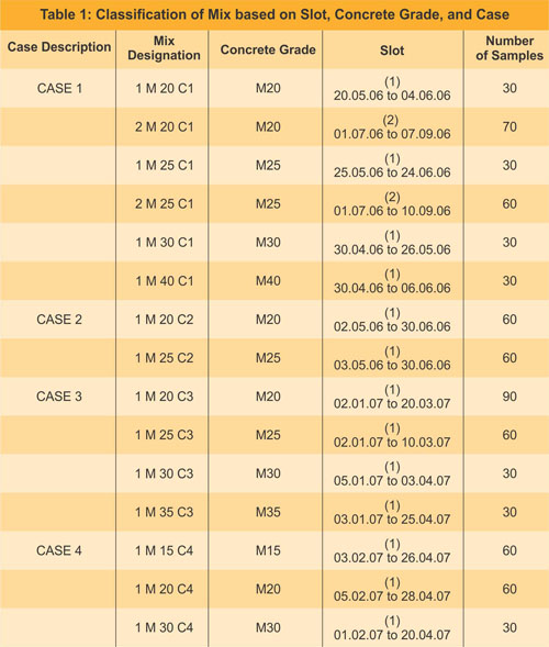
The various concrete mixes collected from Case 1, 2, 3 and 4 have been given a specific designation based on the grade of concrete, slot / batch and specific case from where the batch has been collected. These designations prove to be very useful in referring the concerned mixes during the analysis. For Mix “1 M20 C1,” “1”refers to the slot for which this mix designs is followed (20.05.06 to 04.06.06). “M20” is the specified grade of concrete where “M” is Mix and 20 is the characteristic compressive strength at 28 days which for this case is 20 N/mm2 or 20 Mpa. “C1” represents Case 1. Details of this designation are presented in Table1.

Classification of Mix Based

A comparative presentation of all the samples collected from Cases 1, 2, 3, and 4 along with the calculated mean, plant standard deviation, target mean strength, target mean range and coefficient of variation are presented in table 2. As per Dewar and Anderson, (1988), Target Mean Strength (TMS) = fck + 2 σ…. (1) where fck is the characteristic cube compressive strength at 28 days, σ = plant standard deviation. Target Mean Range (TMR) = 1.128 x assumed standard deviation (plant standard deviation)….. (2).

Comparision of Plant Standard Deviation, Mean, TMS, TMR, and Coefficient of Variation

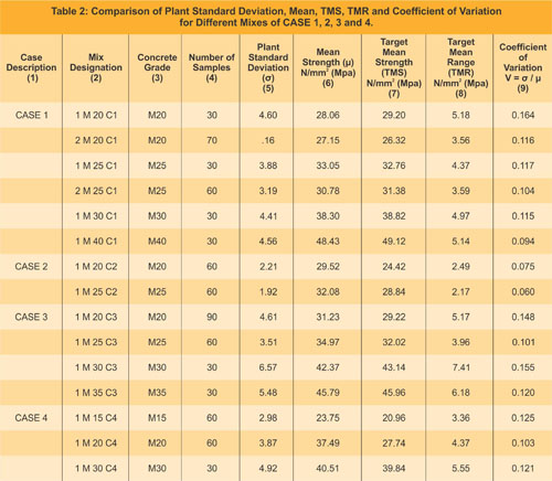
Table 2 has been formulated using Excel wherein the mean strength of the data of each slot for a specified concrete grade is calculated and presented in column (6). Column (5) represents the values of plant standard deviation as obtained from the calculation of the values of the compressive strengths of the collected samples of different batches of the same slot and mix design. It is more logical to use the values of the plant standard deviations for analysis for target mean strengths greater than 27 N/mm2 (Dewar and Anderson, 1988). From the calculated results it is observed that for four case studies under consideration the value of standard deviation obtained in the plant varies from values as low as 1.92 to as high as 6.57. This reflects the fact that a different degree of quality control is maintained by each plant. The value of standard deviation of 1.92 is for a plant which is semi-automatic. Since this plant is not a commercial RMC plant and is set up by a contracting organization to supply concrete for construction of a management institute, location and working conditions of the plant are excellent and most of operating conditions are under control and the quantity of concrete produced, is of range of 600 to 900 cu‎m per month. Due to this limited production they might be able to maintain good degree of quality control, thus having lower standard deviation values. On contrary for a plant as in case 3 located in Delhi which is fully automatic and has latest imported equipment, but is not able to maintain a good degree of quality control, which is reflected from a very high value of standard deviation like 6.57 may be due to the pressure of producing and delivering very high quantity of concrete which may be of the range of 500 to 800 cu‎m per day during peak demands. Thus the present work aims in developing an effective quality monitoring and control model which will definitely benefit the commercial batching plants located in metros and major cities of India which have a target of producing superior quality concrete of quantities as high as 1000 to 1200 cu‎m per day.

Target Mean Strength (TMS) for each mix is calculated as per equation (1) and the Target Mean Range (TMR) as per the relationship TMR = 1.128 σ (Dewar and Anderson, 1988). The CUSUM for range aims in monitoring the difference between two consecutive values of compressive strength obtained and also monitors the difference between highest and lowest value of the strength obtained in a specified grade of concrete of different batches of the same slot produced from same mix design. The coefficient of variation presented in column (9) is a good indicator of the degree of quality control maintained by the plant. As per the results obtained the coefficient of variation varies from 0.06 (Case 2) to 0.164 (Case 1). The average coefficient of variation of Case 1 is 0.118, Case 2 is 0.068, Case 3 is 0.131 and of CASE 4 is 0.116.

These results reflect the fact that amongst the four cases under analysis best quality control is maintained by the plant of Case 2, followed by Case 4, Case 1 and Case 3.

Proposed Quality Control Model for Indian RMC Industry

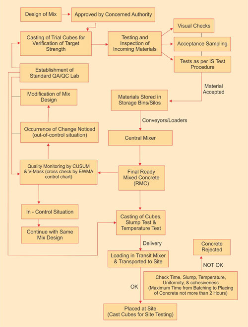
Based on the analysis carried out in this present research, a Quality Control Model which can be widely accepted by the Indian RMC industry has been proposed. The schematic representation of this model is presented in Figrue. 1

Proposed Quality Control Model for Indian RMC Industry

Quality Assurance (QA)/ Quality Control (QC) Team

The QA /QC team for the proposed model should be headed by a QA/QC Manager. He is the key person involved in the decision making process. He should be assisted by QA/QC Incharge whose job is to co-ordinate and implements the QA /QC guidelines and test procedures for the entire batching plant. Minimum two QA/QC Engineers should assist the incharge. The engineers should be involved in physically conducting the tests of the incomming raw materials and the final product ie. RMC. They should be physically present to check that all the equipment are calibrated properly. Also they should carry out the daily or weekly quality monitoring as per the proposed model. The QA/QC Incharge will take decisions about the assignable causes noticed during the monitoring phase. At least four lab technicians should be employed per plant to carry out the sampling and testing.

Establishment of Standard QA / QC Lab

A standard QA /QC lab with latest testing equipment should be established at the plant.

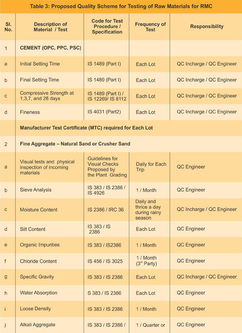
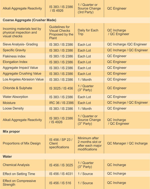
Testing of Raw Materials, Fresh Concrete and Hardened Concrete

The incoming materials particularly raw materials like cement, coarse aggregate 10mm, coarse aggregate 20mm, fine aggregate, admixtures should be subjected to testing as per adopted acceptance sampling plan. A proposed scheme for the basic tests to be conducted for raw materials, fresh concrete and hardened concrete along with their frequency of testing is given in Table 3.

Proposed Quality Scheme for Testing of Raw Materials for RMC

Ready Mixed Concrete Industry

Operation as per Proposed Model

The design of the mix should be carried out by competent authority and should be approved by authorities like Indian Institute of Technology (IIT), National Council of Cement and Building Materials (NCCBM), Council of Scientific and Industrial Research laboratories, Concrete Technology laboratories of National Institute of Technologies etc. The approved mix design for each grade of concrete should be tested in the plant as per plant conditions by casting trial cubes. Any major deviations of strength should be immediately communicated to the concerned authority and necessary rectifications should be carried out immediately.

Admixtures

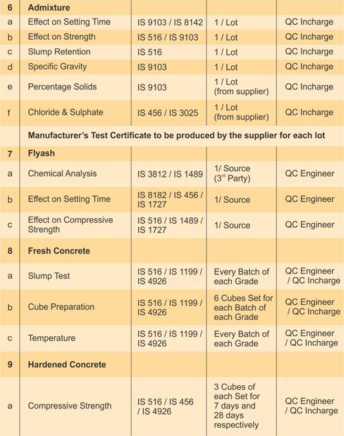
A standard QA /QC laboratory equipped with latest testing equipments should be established at site. Minimum two lab technicians should support two QA /QC engineers. The QA / QC engineers should report to QA / QC Incharge who in turn should report to QA/QC Manager. The incoming raw materials (cement, fine aggregates, coarse aggregates 10mm, coarse aggregates 20mm, flyash, admixtures etc.) should be tested with visual checks as per the testing procedures laid down by the respective QA/QC department of the plant. The raw materials found unsatisfactory in the visual checks should be rejected and as per requirement confirmatory tests should be conducted before rejection. The supplier should be immediately informed about the rejection of his material and should be warned so that if he repeats the same, his contract would be terminated. Standard tests for raw materials, fresh concrete and hardened concrete have to be performed as per Indian Standard (IS) testing procedures. The details of these tests along with the respective IS codes and frequency of testing is given in table

The materials qualifying in the respective tests are accepted and aggregates are stored in respective aggregate storage bins. Cement and flyash should be stored in cement silo and flyash silo respectively. It is desirable to transport the cement in bulkers and directly pump it into the silo through pneumatic pumps. The cement if required to be stored in godowns should be well protected from rains. The godown should be covered on all sides and should be provided with adequate size of lockable entry or exit gates. Cement should always be stored on a plain cement concrete base which is about 200 mm thick or brickwork base which is about 300 mm above the ground. The oldest lot should be used first. It is always better to cover the cement bags with polythene sheets particularly in pre-monsoon and monsoon seasons. The workforce involved in handling cement bags or bulk cement should compulsorily be provided with personal protective equipments like safety helmets, safety shoes hand gloves and safety goggles. During pumping of cement into the silos the workmen should take utmost care so that the cement due to back hammering effect does not create major accidents like severe eye injuries. The workmen should compulsorily wear safety goggles and helmet while working with the pneumatic pumps.

The stored raw materials should be weighed (as per the weights of design mix) in the respective weigh hoppers fitted with load cells. These weighed materials through screw conveyors or loaders should be transported to the central mixer. Measured quantity of water through water meter and admixtures through admixture dispensers should be added into the central mixer after dry mixing of cement, flyash, coarse aggregates and fine aggregates. After addition of water and admixtures the final mixing should be carried out for about 30 seconds. The entire loading process takes about 90 seconds. Thus the ideal cycle time for each of concrete is about 120 seconds. The capacity of each batch may be of 0.5 m3, 1 m3 and 2 m3 depending upon the capacity of the plant.

The RMC thus produced have to undergo tests of fresh concrete like slump tests and corresponding temperatures of the concrete should be noted. If the concrete is produced in summers when the outside temperature is about 40 to 45 degree Celsius the drum of the transit mixer should be covered with wet jute cloth and desirably some ice cubes should be added to the fresh concrete. The slump of the mixes to be placed by concrete pumps should be at least 180mm to 200 mm at the time of pumping. Thus use of flyash in the mix is always desirable for pumpable mixes as flyash due to ball bearing action increases the pumpability of a mix. The slump of concrete to be placed by crane and concrete bucket or by elevator hoists should be about 100 to 120mm at site. Minimum 6 cubes (150mm x 150mm x 150mm) should be prepared for each batch of concrete produced as per standard procedures. The cubes should always be casted in a cool shady place and in no case should the casting procedure be carried out under hot sun. The cubes should be air cooled for about 24 hours and then placed into the curing tank for curing. The curing tank should be completely filled with water and desirably should contain different compartments for 3 days, 7 days and 28 days testing. The fresh cubes should be marked with the specified grade of concrete, date of casting and should be placed in a jute gunny bag and after tying the mouth of the bag and putting a plastic tag of the grade and date of casting of the concrete, the bag should be placed in the desired compartment of the curing tank. Generally if the requirement is that the concrete needs to be tested for 7 days and 28 days compressive strength, then 3 cubes should be packed in the jute gunny bag and placed into the compartment for 7 days curing and other 3 cubes should be placed in the compartment for 28 days curing. As per client requirement if 3 days strength also needs to be tested then total 9 cubes should be casted. Following a systematic procedure of casting and curing the cubes improves the degree of quality control of the plant. The cubes should be tested in hydraulically operated compressive strength testing machine and desirably the manually lever operated strength testing equipment should be avoided. Care should be taken to ensure that the cube is uniformly seated before application of the load and the rate of loading should be uniform and desirably 140 kg /cm2/min. The failure load of the three cubes should be noted separately and the corresponding compressive strength should be calculated. The average of three cube strengths can be considered as the observed strength of a sample.

The fresh concrete thus prepared is loaded in transit mixers and transported to respective sites. The time from batching to placing of the concrete at the site should not exceed 2 hours. If the concrete is transported in summers the drum of the transit mixer should be covered with wet jute cloth and during extremely high temperatures ice cubes should added in the concrete. No additional water should be added in the concrete enroute. Before placing, the concrete should be tested for desirable slump, temperature, uniformity and cohesiveness and if found ok should be placed at the respective site.

The 7 days and 28 days strength obtained should be monitored using CUSUM and V-mask. This technique should be used as a daily monitoring tool and when the results of about four to five samples are obtained the data should be plotted using Excel / SPSS software where the x- axis of the graphical representation of the CUSUM plot (mean strength, range and correlation) represents sample number and the corresponding y- axis represents the CUSUM value in N / mm2 or Mpa. The V-mask plotted in a transparent paper should be superimposed on the obtained CUSUM plot by placing the lead point of the mask on each and every obtained CUSUM value starting from the first sample. If the plot remains within the boundary of the mask, the process is in control. If the plot crosses the boundary of the mask, a significant change has occurred in the process mean and an action is required. The root cause of the problem need to be investigated and accordingly action should be taken. A change in cement content can be calculated by the empirical relationship proposed by Dewar and Anderson (1988), and trial cubes can be casted and tested with the modified mix design value. The proposed Quality Control Model for Indian RMC Industry is presented in Figure 1.

Conclusion

RMC emerges to be an advantageous material in congested sites where setting up of a mixing plant is difficult. Presently construction industry including real estate developers are opting for RMC of grades M20, M25, M30, M35, M40, M50 and even higher grades. However, in absence of proper and effective quality monitoring systems in most of the batching plants in India, they are lagging behind from their western counterparts in terms of operational procedures, product quality and economy in manufacture of concrete. Hence there is a need to analyze the applicability of scientific quality monitoring techniques to RMC in India. The proposed Quality Control model for Indian RMC industry is a SQC based, simplified user friendly model, which if adopted, we think, would make Indian RMC industry much more organized and efficient in terms of production and operation.

Acknowledgment

Author highly acknowledges the cooperation and help of the RMC batching plants of Ahmedabad and Delhi under study, in providing necessary information for this research work.

References

  • Dewar, J.D. and Anderson, R. (1988) Manual of Ready Mixed Concrete Blackie and Son Ltd., Glasgow and London.
  • Box, G. (1994) “Role of Statistics in Quality and Productivity Improvement” Journal of the Royal Statistical Society, Series A, Part 2, pp. 209-229
  • Keats, J.B. and Montgomery, D.C. [Editors] (1996) Statistical Applications in Process Control Marcel Dekker, Inc., New York.
  • Montgomery, D.C. (1985), Introduction to Statistical Quality Control John Wiley & Sons, Inc, New York.
  • Montgomery D.C. and Woodall, W.H. (1997) “A Discussion on Statistically Based Process Monitoring and Control.” Journal of Quality Technology Vol. 29, pp. 121-162.
  • Sarkar, D. and Bhattacharjee, B. (2003) “Quality Monitoring of Ready Mixed Concrete Using Cusum System” Indian Concrete Journal, Vol 7, pp. 1060-1065.
  • Woodall, W.H. (1986) “The design of CUSUM quality control charts.” Journal of Quality Technology, Vol. 18, pp. 99-102.
THANKS TO 

Er.SP.ASWINPALANIAPPAN., M.E.,(Strut/.,)
Structural Engineer
Madras Terrace Architectural Works