Wednesday 23 August 2017

Earthquake zones of India

                                                               Earthquake zones of India
                                                                    Press data Bureau
                                                                 Government of India
                                                            Ministry of natural science

Earthquake Prone Zone


Bureau of Indian Standards, supported the past unstable history, classified the country into four unstable zones, viz. Zone-II, -III, -IV and –V. Of these, Zone V is that the most seismically active region, whereas zone II is that the least. The changed Mercalli (MM) intensity, that measures the impact of the planetquakes on the surface of the earth, broadly speaking related to varied zones, is as follows:

Seismic Zone Intensity on millimetre scale

II (Low intensity zone)                                   VI (or less)
III (Moderate intensity zone)                         VII
IV (Severe intensity zone)                              VIII
V (Very severe intensity zone)                       IX (and above)

Broadly, Zone-V contains of entire northeastern Asian nation, components of Jammu and geographical region, Himachal Pradesh, Uttaranchal, Rann of tannic acid in Gujarat, components of North Bihar and Andaman & Nicobar Islands. Zone-IV covers remaining components of Jammu & geographical region and Himachal Pradesh, Union Territory of metropolis, Sikkim, northern components of province, Bihar and West Bengal, components of Gujarat and little parts of geographic area close to the geographical area and Rajasthan. Zone-III contains of Kerala, Goa, Lakshadweep islands, and remaining components of province, Gujarat and West Bengal, components of geographic region, Rajasthan, Madhya Pradesh, Bihar, Jharkhand, Chhattisgarh, geographic area, Orissa, province, Tamilnadu and Karnataka. Zone-II covers remaining components of the country.

Further, as a part of pre-disaster readiness live, Government of Asian nation has additionally completed unstable microzonation studies of a number of the most important cities within the country like, Jabalpur, Guwahati, Bangalore, larger Bharuch in Gujarat, Jammu in J & K, Shillong in Meghalaya, city in Tamilnadu and geographical region state. These studies involving preparation of geologic, morphologic and land use maps followed by drilling, geologic work, normal penetration take a look at and geology studies to demarcate the zones of least to most harm prone areas at intervals the urban areas helps the individual city and country coming up with agencies to formulate perspective coming up with at intervals the earthquake impact minimisation efforts.

            This info was given by Minister of Earth Sciences Dr. Harsh Vardhan in Lok Sabha nowadays.

KSP/SRD


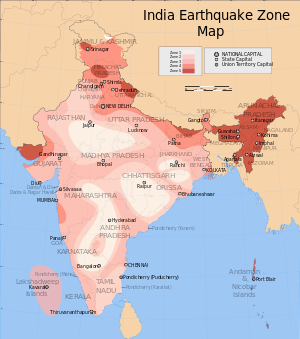
The Indian subcontinent has a history of devastating earthquakes. The major reason for the high frequency and intensity of the earthquakes is that the Indian plate is driving into Asia at a rate of approximately 47 mm/year.[1] Geographical statistics of India show that almost 54% of the land is vulnerable to earthquakes. A World Bank and United Nations report shows estimates that around 200 million city dwellers in India will be exposed to storms and earthquakes by 2050.[2] The latest version of seismic zoning map of India given in the earthquake resistant design code of India [IS 1893 (Part 1) 2002] assigns four levels of seismicity for India in terms of zone factors. In other words, the earthquake zoning map of India divides India into 4 seismic zones (Zone 2, 3, 4 and 5) unlike its previous version, which consisted of five or six zones for the country. According to the present zoning map, Zone 5 expects the highest level of seismicity whereas Zone 2 is associated with the lowest level of seismicity.

Center for Seismology


Center for geophysics, Ministry of Earth Sciences is nodal agency of state of India handling numerous activities within the field of geophysics and allied disciplines. the foremost activities presently being pursued by the middle for geophysics embrace, a) earthquake watching on 24X7 basis, as well as real time unstable watching for early warning of tsunamis, b) Operation and maintenance of national seismologic network and native networks c) seismologic information centre and data services, d) unstable hazard and risk connected studies e) Field studies for earth tremor / swarm watching, website response studies f) earthquake processes and modelling, etc.[3] The MSK (Medvedev-Sponheuer-Karnik) intensity loosely related to the varied unstable zones is VI (or less), VII, VIII and IX (and above) for Zones two, 3, 4 and 5, severally, resembling most thought of Earthquake (MCE). The IS code follows a twin style philosophy: (a) underneath low likelihood or extreme earthquake events (MCE) the structure injury shouldn't end in total collapse, and (b) underneath additional oft occurring earthquake events, the structure ought to suffer solely minor or moderate structural injury. The specifications given within the style code (IS 1893: 2002) don't seem to be supported elaborate assessment of most ground acceleration in every zone employing a settled or probabilistic approach. Instead, every zone issue represents the effective amount peak ground accelerations that will be generated throughout the utmost thought of earthquake ground motion therein zone.

Each zone indicates the consequences of associate degree earthquake at a specific place supported the observations of the affected areas and might even be delineated  employing a descriptive scale like changed Mercalli intensity scale[4] or the Medvedev–Sponheuer–Karnik scale.[5]

Zone 5


Zone five covers the areas with the best risks zone that suffers earthquakes of intensity MSK IX or larger. The IS code assigns zone issue of zero.36 for Zone five. Structural styleers use this issue for earthquake resistant design of structures in Zone five. The zone issue of zero.36 is indicative of effective (zero period) level earthquake during this zone. it's named because the terribly High harm Risk Zone. The region of Jammu and Kashmir, the Western and Central chain of mountains, North and Middle province, the North-East Indian region, the Rann of tannin and therefore the Andaman and Nicobar cluster of islands fall during this zone.

Generally, the aras having lure rock or volcanic rock rock are susceptible to earthquakes.

Zone 4

This zone is termed the High injury Risk Zone and covers areas vulnerable to MSK VIII. The IS code assigns zone issue of zero.24 for Zone four Jammu and geographic area, Himachal Pradesh, Uttarakhand, Sikkim, the components of Indo-Gangetic plains (North geographic region, Chandigarh, Western Uttar Pradesh, Terai, North geographical region, Sundarbans) and therefore the capital of the country Delhi fall in Zone four. In Maharashtra, the Patan space (Koynanagar) is additionally in zone no-4. In Bihar the northern a part of the state like Raxaul, close to the border of Asian nation and Nepal, is additionally in zone no-4.

Zone 3

This zone is classified as Moderate Damage Risk Zone which is liable to MSK VII. and also 7.8 The IS code assigns zone factor of 0.16 for Zone 3.

Zone 2

This region is liable to MSK VI or less and is classified as the Low Damage Risk Zone. The IS code assigns zone factor of 0.10 (maximum horizontal acceleration that can be experienced by a structure in this zone is 10% of gravitational acceleration) for Zone 2.

Zone 1


Since the current division of India into earthquake hazard zones does not use Zone 1, no area of India is classed as Zone 1.
Future changes in the classification system may or may not return this zone to use.

Dynamic Testing of Gopuram Structure of Nalanda University beneath simulating Earthquake Hazards

Dynamic Testing of Gopuram Structure of Nalanda University beneath simulating Earthquake Hazards

Department of technology has undertaken a Dynamic check on Gopuram Structure on distinctive Shock Table Facility. Gopuram could be a one in all the necessary structure for AN forthcoming Nalanda University field at Rajgir, Bihar.

The check was witnessed by Representatives of Nalanda University Management man. Joy et al, Prof. Y. M. Desai from IITBombay, Mr. Rajiv from Vastu Shilpa Consultants, Prof. V. R. crowned head from Vinod crowned head Consulting Engineers Pvt. Ltd., Mr. Keyur Sharda from Kesarjan Building Centre non-public restricted together with Director of IT-NU, college Members and M. Tech. (CASAD) Semester-II and Semester-IV students of technology Department.

Pavement Stretch constructed using Alkali activated concrete pavers by the department of Civil Engineering


 Pavement Stretch constructed using Alkali activated concrete pavers  by the department of Civil Engineering

        A rural pavement stretch of size two.5 m × sixteen m exploitation Alkali activated concrete paver blocks is made at Jaspur Village, Kalol, Gandhinagar by the department of technology, Institute of Technology, Nirma University. The paver blocks area unit created exploitation zero cement concrete (alkali activated concrete) and used for the development of the agricultural pavement having low traffic volume.

     The higher than work is one amongst the result of the research titled “Application of formed product created exploitation Bottom Ash And ash For Rural Pavements And different Infrastructure In India”. The aforementioned project may be a cooperative research between University of Victoria, North American nation & Nirma University, India and is approved by IC-IMPACTS (India-Canada Centre for Innovative Multidisciplinary Partnerships to Accelerate Community Transformation and Sustainability) Centres of Excellence.

      The paver blocks wont to create the pavement area unit of “Unipaver”/“Zigzag” form & of thickness of sixty metric linear unit. The alkali activated concrete paver blocks have earned the compressive strength up to forty MPa when the completion of close action for the time length of 28-days.
      The alkali activated concrete paver blocks contained a mix of ash and Bottom ash, Coarse mixture restricted to size of ten metric linear unit, Sand, hydroxide & soluble glass. ash & Bottom ash area unit the waste product of the thermal power plants. hydroxide & soluble glass used for the paver blocks area unit of business grade. Therefore, it's anticipated that the alkali activated paver blocks area unit economical as compared thereto of cement concrete paver blocks.

        The in small stages procedure of creating the pavement stretch consists,
1) Preparation of around 1200 Nos. of alkali activated concrete paver blocks at concrete casting yard of technology department, Nirma University.
2) Excavation of size 2.5 m × sixteen m having depth of two hundred metric linear unit exploitation power shovel.
 3) birth of PCC of depth a hundred metric linear unit having grade of concrete of M10.
 4) birth of twelve in. edge stones around edges of the pavement.
 5) birth of forty metric linear unit depth sand bedding.
6) birth of paver blocks having depth of sixty metric linear unit in textile bond.
 7) Joint waterproofing between paver blocks exploitation compactor.

Friday 11 August 2017

Units of Measurement iv our area

Units of measurement used in past and present surveys are
For construction work: feet, inches, fractions of inches (m, mm)
For most surveys: feet, tenths, hundredths, thousandths (m, mm)
For National Geodetic Survey (NGS) control surveys: meters, 0.1, 0.01, 0.001 m
The most-used equivalents are
1 meter=39.37 in =3.2808 ft
1 rod =1 pole=1 perch=16.5ft(5.029 m)
1 engineer’s chain =100 ft =100 links (30.48 m)
1 Gunter’s chain= 66 ft (20.11 m) =100
Gunter’s links(lk)=4 rods=0.020 km
1 acre=100,000 sq (Gunter’s) links=43,560ft2= 160 rods2=10 sq (Gunter’s) chains=4046.87m2=0.4047 ha
1 rood=1011.5 m2=40 rods2
1 ha= 10,000 m2=107,639.10 ft2=2.471 acres
1 arpent=about 0.85 acre, or length of side of 1 square arpent (varies) (about 3439.1 m2)
1 statute mi=5280 ft=1609.35 m
1 mi2=640 acres (258.94 ha)
1 nautical mi (U.S.)= 6080.27 ft= 1853.248 m
1 fathom=6 ft (1.829 m)
1 cubit=18 in (0.457 m)
1 degree=0.01745 rad=60 min =3600 s
sin 1 =0.01745241
1 rad = 57.30 degree

Detailed Units – Convert Units

Following table shows how can we convert various most commonly used units from one unit system to another.

Units to convert
Value
Square foot to Square meter
1 ft² = 0.092903 m²
Foot per second squared  to Meter per second squared
1 ft² = 0. 3048 m²
Cubic foot to  Cubic meter
1 ft³ = 0.028316 m³
Pound per cubic inch to Kilogram per cubic meter
1 lb/in³ = 27679.9 047102 kg/m³
Gallon per minute = Liter per second
1 Gallon per minute = 0.0631 Liter per second
Pound per square inch = Kilopascal
1 Psi (Pound Per Square Inch)  = 6.894757  Kpa (Kilopascal)
Pound force = Newton
1 Pound force = 4.448222 Newton
Pound per Square Foot to Pascal
1 lbf/ft= 47.88025 Pascal
Acre foot per day = Cubic meter per second
1 Acre foot per day= 1428 (m3/s)
Acre to square meter
1 acre = 4046.856 m²
Cubic foot per second = Cubic meter per second
1 ft³/s = 0.028316847 m³/s

Measurement Units

Measurement units and standards square measure totally different in several countries however to keep up a customary, SI units square measure largely used once addressing comes involving {different|totally totally different|completely different} countries or maybe different states. tiny comes are often through with the regionally used unit system however once the project is huge, one commonplace unit system is to be used.

Two most typical system employed in the u.  s. square measure

United States Customary System (USCS)
System International (SI)

But the SI unit system is additional wide used everywhere the planet. Following is that the table that shows however you'll be able to convert USCS measurements in SI measurements. ( simply multiply the USCS quantity with the corresponding figure given in table below


USCS unit X Factor = SI unitSI symbol
Square foot X 0.0929 = Square meterM2
Cubic foot  X 0.2831 = Cubic meterM3
Pound per square inch X 6.894 = KilopascalKPa
Pound force X 4.448 =  NewtonNu
Foot pound torque X 1.356 = Newton meterN-m
Kip foot X 1.355 = Kilonewton meterLN-m
Gallon per minute X 0.06309 = Liter per secondL/s
Kip per square inch X 6.89 = MegapascalMPa

Thursday 10 August 2017

Bar Bending Schedule (BBS)

What is meant by Bar Bending Schedule (BBS)

Bar Bending Schedule, commonly referred to as “BBS” is a comprehensive list that describes the location, mark, type, size, length and number, and bending details of each bar or fabric in a Reinforcement Drawing of a Structure.
This process of listing the location, type and size, number of and all other details is called “Scheduling”. In context of Reinforcement bars, it is called bar scheduling. In short, Bar Bending Schedule is a way of organizing rebars for each structural unit, giving detailed reinforcement requirements.
REINFORCEMENT (R/f)
  • Introduction
Reinforced concrete is the most commonly used structural material in engineering construction. Although concrete is strong in resisting compressive stress, it is weak intention. Hence to withstand tensional stresses, steel is need in concrete. The reinforcement in concrete may be simple bars or rods bend and tied to a given schedule with stirrups. The nominal diameters of bars used at site were Y10, Y12, Y16, Y20, Y25 and R6.
Steel is supplied in two basic types.
1. Mild steel (250 N/mm2)
2. Tor steel (460 N/mm2)
  • Bar code            
Indication of Reinforcement in Drawings
Engineering drawings is a language to communicate with details. Therefore there is a standard to indicate reinforcement in drawing such as,
5Y10- 001- 150:-Which means 5 Number of Tor steel, 10mm Diameter, Bar mark 001, At 150mm CRS. At                                                      bottom face.
Bar location can be vary as follows:
Notation for Slab-
T1 -Top outer layer, T2 -Top second layer
B1 -Bottom outer layer, B2 -Bottom second layer
  • Cutting and Bending of Bars
      There is a steel yard in the site for storing, cutting and bending of bars. Reinforcement bars are cut into required lengths and bent into required shapes shown on the bar schedule either manually or by means of machinery.
       In manual operations, laborers used the bar bending bench on which strong nails are fixed and GI pipes with suitable lengths to bend the bars. That is used for smaller diameter bars. For bending of larger diameter bars, bar bending machine is used. After bending all reinforcement bars were bundled and clearly numbered according to the bar mark so that steel fixers will not face any difficulty when fixing them.
Picture1
Fig.1 :- Bar bending work
  • Prepare bar schedule (important considerations)
 Reinforcement Bar Schedule
      Reinforcement Bar Schedule is prepared in a standard manner. The bar bending schedule should be prepared and it should be submitted to the steel bar steel yard to cut and to bend the bars for purposes, because bar bending schedule is the simplest of details what is in the drawings which can easy to under stand for bar benders. It contains all the details needed for fabrication of steel.Those details are bar mark, bar type and size, number of units, length of a bar, shape code, distance between stirrups (column, plinth, beam) etc.
Advantages of the Bar Schedule:
  • By preparing a bar schedule, and arranging them according to the lengths, it will lead to an economical bar cutting, reduce the bar cutting wastages.
  • It is easy to manage the reinforcement stock required for identified time duration.
  • It will help to fabrication of R/F with structure.
Calculating weight of the steel
 While prepared the bar schedule, we used the unit weight of reinforcement bar.
Nominal Diameter of the bar (mm)Unit weight (kg/m)
R60.222
R100.610
T100.617
T120.888
T161.580
T202.469
T253.858
T326.313
Table- Unit weight of the bar
It is necessary to be careful about length when preparing bar schedules. In case of bending, bar length will increased at the bending positions.
  • Minimization of bar cutting wastage
 In the site several steps were adopted for that purpose. Those are, Use of 12m long r/f bars rather than using shorter bars. For example 6m bars off cuts of 12m bars were used to prepare stools, separators etc.
  • Off cuts of larger diameter (25mm) bars-for spacer bars
  • Off cuts of smaller diameter (10mm) bars-for stools
  • Lapping
     Lapping is required when a bar isn’t long enough or a joint is required. Bars may be deliberately left short for constructability and transportation concerns. The preferred method of lapping where the two bars overlap each other for some minimum distance. This distance is called Lap length. These two bars are in physical contact and wired together. It does not represent an actual bend in the bar.
Picture20
Fig 2: Lapping and cranking detail
  • Other material used In Reinforcement Works
Binding Wires
R/f bars are jointed with using wires which is called “binding wires”. Hackers are used to bind these wires.
Cover Blocks
     They were made up of 1:3 ratio of cement mortar. Cover blocks should be immersed in water for 28 days to get the maximum strength.All the beams were checked to ensure adequate cover blocks are provided to the bottom and sides of the beam reinforcementMain bars of the columns were adjusted to ensure the covering requirements before concreting. Stools of correct height were used to maintain the require gap between top and bottom reinforcement nets and cover blocks were also provided to bottom reinforcement.
Picture21
Fig 3: Cover blocks
Cover to Reinforcement
  • Concrete cover for steel bar is much necessary to protect the steel against corrosion (rusting) and to provide resistance against fire.
  • For R.C.C. Slab and staircase the cover is 20 mm.
  • For RCC column the cover (To stirrups) 30mm.
  • In case of underground structures the cover is 50 mm.
  • In case of beams in superstructure (To stirrups) the cover is 25mm.
  • In case of ground resting floor slab (Top surface) and retaining walls the cover is 50m.

  • Stirrups
       Stirrups will be required at areas of high shear, such as bearing points and below large point loads.  Increasing concrete beam spans, to reduce the need for additional piers, has resulted in the need for the use of steel stirrups. Concrete beams vary in depth.  The deeper the beam, the more shear capacity.  When the depth is not adequate, steel stirrups must be added to increase the shear capacity of the beam.
       These stirrups are usually one piece of steel that is bent into a rectangular shape. The stirrup typically wraps around the bottom and top bars of the beams. A designer should specify the size, spacing and location along the length of the beam where the stirrups are required.  In my site specify the stirrup dimensions in our section drawings, so that the stirrup can be manufactured prior to installation. The installer should be careful to fabricate the stirrup from one piece of steel and adequately overlap each end.
Picture22
Fig 4: Bar Schedule for stirrups
  • Stools
Stools are used to separate the top reinforcement mesh and bottom reinforcement mesh. Dimension of the Stools could be change as requirement. Those should be strength enough to bear the loads without changing the gap of two layers. 12 mm or 16 mm bars are used to make the stools.
Picture24Picture23
Fig 5: Stools
Important  points to be checked.
  • Size of the bar
  • Length of the bar
  • Location of the bar
  • Position of the bar
  • Number of bars
  • Lap lengths
  • Correct cover of reinforcements and cover blocks
  • Spacing (in slab reinforcements and stirrups)
  • Direction of the bars (in slabs)
  • Dimensions of the element thickness of a slab, depth and width of a beam, etc…)
Columns, Beams, Slab Reinforcement
  • Column Reinforcement
      The column reinforcement bars should be stared from the Footing. The upper column reinforcement bars are cranked at the laps and connected. Special care should be taken in this to ensure the lap lengths. After erection of main reinforcements, cover blocks were attached to column reinforcements to maintain the required cover for column reinforcement. Most of Columns centers were located at intersections of grid lines.
Stirrup spacing
       According to the Column reinforcement details drawing the reinforcement detail for a typical internal Column, from to basement to ground floor is as follows.
       Column stirrups were tightened up to beam bottom level and rest is tightened once beam reinforcement is fabricated. So Bar benders was instructed how to provide the stirrups. Mark the stirrup spacing from the basement floor level in the Column main bars with a chalk as follow the detail drawing.
E.g.:
Picture25Picture26
Fig 6:  Section of column Reinforcement
Bar Schedule for Footing, Column up to DPC and Column.
E.g-
Picture2
Footing
Size – 1000 x 1000 x 250
R/f Details – Y10 at 225 C/C (B) Both ways
Picture3
Table 1: Schedule for Footing, Column up to DPC and Column
  • Beam Reinforcement
   Beam is a horizontal structural member resting on two or more supports. It is used to transfer the load to the columns.Beam reinforcements are arranged after the construction of beam and slab formwork.
The method adopted for the arrangement of beam reinforcements is as follows:
    First the top most reinforcement bars are hung over the beam formwork and then the stirrups are placed and bound at correct positions. Thereafter the bottom reinforcement bars are placed and bound to the stirrups. After that the rest of the reinforcement bars and tension bars are inserted into the cage according to structural drawings. Then cover blocks are fixed to bottom and side reinforcements before placing the concrete.
Consideration for give lap length
Picture27
Fig 7: Reinforcement for beams
    Top reinforcement of the beam shall be lapped at the middle of the span of between two supports. Bottom reinforcement of the beam shall be lapped at the end of the span of the two supports. Considering the region where the maximum bending movement is existing.
       Lapping is did the place which the tension is didn’t act. Normally 2/3 of the length is choosing for lapping. When lapping top & bottom re-bar, it is better to follow the following method.Otherwise, it might cause to reduce the concrete covering thickness of the topmost& bottom most slab reinforcement.
Picture28
Fig 8: Reinforcement  for beams
Anchorage (bond) in concrete
Because the actual bond stress varies along the length of a bar anchored in a zone of tension. The main requirement for safety against bond failure is to provide a sufficient extension of the length of the bar beyond the point where the steel is required to develop its yield stress and this length must be at least equal to its development length. However, if the actual available length is inadequate for full development, special anchorages must be provided, such as bends, hooks.
E.g- (Anchorage length 45 d (for top bars),12 d (for bottom bars)) where “d”, “Ø”  is diameter of the Bar.
Anchorage length Calculation
E.g.:-  20 mm diameter bar
Picture29
Fig 9: Anchorage length
Bending length = 112.5- (Cover (25 mm)+ Stirrup (10 Ø))
= 72.5mm
Anchorage length (x) = 45 x diameter of the bar(20 Ø)
= 827.5 mm
Bar schedule for Beam
Picture6
Picture7
Table 2: Bar Schedule for Beam
  • Slab Reinforcement
Slab reinforcement is the most important part of the structure. It is important to have an idea on slab reinforcement detailing. Following basic thing could be studied in drawing on slab reinforcement detailing.

Distribution bar reinforcement

Small diameter bars, usually at right angles to the main reinforcement, intended to spread a concentrated load on a slab and to prevent cracking.Standard method used for indicated the slab top & bottom reinforcement.
Picture30
First step of the fixing of slab reinforcement was placed the bottom most R/F (B1) of the slab. Before placing the re-bar, correct spacing given in the detailing drawing were marked by using piece of choke on the slab formwork. After placed the (B1) R/F then placed the (B2) R/F and bound both R/F layers together by using binding wire. Then cover blocks for bottom most R/F were fixed. Finally, Top R/F (T2), Topmost R/F (T1)& distribution bars were placed according to the drawing and fixed together by using binding wire. Then Stools were fixed to separate the both top & bottom R/F net as fulfilled the thickness.
DCIM101MEDIA
Fig 10:  Reinforcement of a slab
Bar crank
Bar cranking is the process of bending up the bottom steel bars in upward direction. It is mainly to prevent upward bending moment near the joint. Also useful for attaching stirrup bar effectively. Cranking is also used in two way slabs.
  • Bar schedule for Slab
Picture8
Picture9
Table 3 : Bar schedule for Slab
  • Bar schedule for some other structures
 Bar schedule for Plinth 
Picture4
Picture33
Table 4: Bar schedule for Plinth
Bar schedule for Stiffener column, Sill beam and Lintel beam
Picture10
Picture11
Picture31
Table 5: Bar schedule for Stiffener column, Sill beam and Lintel beam

Formation Of Bar Bending Schedule

A list of reinforcement bars is called bar bending schedule (or schedule of bars), a given RCC work thing, and is displayed in a form of tabular layout for simple graphical reference. The following table epitomizes all the required details of bars such as diameter, shape of bending, length of each bent and straight portions, angles of bending, total length of each bar, and number of each sort of bar. During the preparation of an estimate of quantities this information will help unconditionally.
The figure below portrays the shape and proportions of hooks and bends in the reinforcement bars – these are customary proportions that are attached to:
(a) Length of one hook = (4d ) + [(4d+ d )] – where, (4d+ d ) relates to the curved portion = 9d.
(b) The supplementary length (la) that is introduced in the plain, straight end-to-end length of a reinforcement bar owing to being bent up at θ° say 30° to 60°, but it is usually 45°) = l1 – l2 = la
Where,
formulaformula

We get different values in respect to the θ° = 30° 45° 60° as follows :
formula
The following figure demonstrates the method to determine the length of hooks and the total length of a given steel reinforcement.
Formation Of Bar Bending Schedule