Thursday 3 September 2020

The evolution of composite flooring systems: applications, testing, modeling and Eurocode design approaches

 The evolution of composite flooring systems: applications, testing,
modeling and Eurocode design approaches


Steel–Concrete Composite (SCC) structural systems are increasingly used in the construction industry and becoming the subject of intensive research by the world's leading universities and companies because of their efficient material usage. This review paper summarises some historic and recent developments as well as the new trends for SCC systems. 

It presents the design philosophy and specific definitions for basic structural elements, including composite beams and slabs with emphasis on the applications, static tests, modeling techniques, design approaches as well as current design limitations. 

This paper concludes with a call for more research for the improvement of Eurocode 4, which in turn can help the fast-growing construction industry to take full advantage of the benefits of composite construction techniques implemented with safety.


© 2019 The Authors. Published by Elsevier Ltd. This is an open-access article under the CC BY license


(http://creativecommons.org/licenses/by/4.0/).


Thanks to 

Elsevier


Authors

Inas Mahmood Ahmed, Konstantinos Daniel Tsavdaridis ⁎


Er.SP.ASWINPALANIAPPAN., M.E.,(Strut/.,)
Structural Engineer


Experimental investigation of long-span cold-formed steel double-channel portal frames


Experimental investigation of long-span cold-formed steel double-channel portal frames


Highlights

Full-scale experiments on a series of long-span cold-formed steel portal frames

Failure due to column global buckling initiated at the knee brace connection.

Connection design greatly affects overall frame strength and stiffness.

Column base in-plane rotational stiffness was quantified.

Abstract

Cold-formed steel haunched portal frames are popular structures in industrial and housing applications. They are mostly used as sheds, garages, and shelters, and are common in rural areas. Cold-formed steel portal frames with spans of up to 30 m (100 ft) are now being constructed in Australia. As these large structures are fairly new to the market, there is limited data on their behavior and design recommendations. An experimental program was carried out on a series of portal frame systems composed of back-to-back lipped channels for the columns, rafters, and knee braces. The system consisted of three frames connected in parallel with purlins to simulate a free-standing structure, with a span of 14 m (46 ft), a column height of 5.3 m (17 ft), and an apex height of 7 m (23 ft). Several configurations were tested including variations in the knee connection, sleeve stiffeners in the columns and rafters, and loading of either gravity only or combined horizontal and gravity loads. Deflections were recorded at various locations to measure global and local movements of the structural members. A total of eight frames with unbraced columns were tested and one frame with braced columns. Experimental results are presented herein including frame strengths and failure modes for the various frame configurations and loading conditions, as well as quantified moment-rotation relations for the column base connection. The contributions and effects of the different knee connections and sleeve stiffeners are presented. The overall frame behavior of these structures and suggested design considerations are discussed.


Keywords

Cold-formed steel
Steel portal frames
Thin-walled structures
Experimental methods


Thanks to 

ScienceDirect


Author links open overlay panelH.B.Blu   & K.J.R.Rasmussen


Er.SP.ASWINPALANIAPPAN., M.E.,(Strut/.,)
Structural Engineer

Tuesday 1 September 2020

Tips for Design of RCC Concrete Beams


Tips for Design of RCC Concrete Beams


If you are new to the design of RCC Concrete beams or any structural members you might find it difficult because what we learn from books during civil engineering studies is different from what is practiced in the construction field. You shouldn’t worry “that” much because both analyzing and designing of structural members is easy once you understand industrial practices and get some experience. Here I am going to give a few tips for the design of RCC Concrete Beams.

Tips for Design of Size, Shape, and Span of RCC Beams

  1. Keep the width of the beam minimum. Some commonly used beam widths are 200, 230, and 300 for practical, structural, and aesthetic reasons.
  2. For plinth, beams assume overall depth from span/15 to span/18
  3. For Tie, beams assume overall depth from span/18 to span/20
  4. For Floor, beams assume overall depth from span/12 to span/15
  5. Design RCC Concrete beam section based on the maximum moment and shear force.
  6. Mu/bd^2 can go up to 6 in case of the heavy beam with long span
Epoxy coating steel bar tar based brush type epoxy coating
Pic:- Amaravathipudur, Andra Pradesh

Tips for Steel Reinforcement Design of RCC Beams

  1. Use smaller sized bars for good efficiency.
  2. For simply supported beam at least 1/3 of positive reinforcement should extent along the same face of the member into support to the length equal to Ld/3
  3. In case of the continuous beam at least 1/4 of positive reinforcement should extend along the same face of the member into support to the length equal to Ld/3
  4. The maximum spacing of stirrups shall be 0.75 times the effective depth so restrict the spacing of the stirrups to 225mm. (300*0.75=225)
  5. Curtailment length shall be checked with the development length
  6. When using two lines of reinforcement keep the larger diameter bars on the outer layer for maximum efficiency
  7. Provide hanger bars at the intersection of Main and Secondary beam for a cushion.
  8. Check the torsion of the main beam when the secondary beam rests on it.
  9. Increase the reinforcement in the support and increase the developmental length by 25% in case of the cantilever
  10. Learn to use T-Beam and L-beam design instead of Rectangular RCC concrete beam, if possible, for maximum design and cost efficiency and to avoid compression reinforcement.

Er.SP.ASWINPALANIAPPAN., M.E.,(Strut/.,)
Structural Engineer

Step by step method to Construct RC Residential House in India


Step by step method to Construct RC Residential House in India


Many houses are constructed as a framed structure because of its strength, faster construction, and feasibility for future modification and extension. In this article, we are going to discuss how to construct an RCC residential house in India. This will be very useful for entry-level engineers to understand the different processes and steps involved in the construction of the house in India.

Construct RC Residential House

Needs and specifications

First, the client will approach the engineer and provide the needs and expectations he/she wants in the building. Then the engineer will suggest ideas and discuss possibilities to bring the needs of the client to reality.

After deciding the type of the house, built-up area, no of rooms, and other utilities, the engineer will give a rough estimate of the cost and time of completion of the project.

Site Visit

  • The engineer and Client will visit the site to study the site.
  • Site clearance will be performed to remove the stones, plants, etc..,
  • The site will be leveled and compacted. Now the site is ready for construction.

Preparation of Plan to construct a house in India

  • Engineer (or architect) will prepare the best plan to construct a house in India which fulfills the client's needs.
  • The engineer will decide the specifications.
  • A “plan blueprint” will be created and sent to the local government body like the panchayat union, municipality, or corporation for getting approval. Blueprint plan will contain Plan, section and elevation of the house along with site plan, septic tank details, area details, sizes of items like doors, windows and ventilators and area details like plot area, built-up area, etc..,

Also Read: How to get a building permit in India? – Required Documents, Plans and application fees

Transfer of loads in Framed building

Slabs and floors transfer the like furniture and others to the beams which in turn transfer the load to the columns. Columns will carry the total load of the structure to the footings and finally, through footings load will be distributed to the soil. In a framed structure, walls only carry the self-weight. The load from the beam will not be transferred to walls.

Design of Building

  • The engineer will prepare the structural design of the building by following design procedures, National Building code(NBC), and IS456 codebook. Many experienced engineers use empirical methods for design if the building is small.
  • Sizes of the different members like beams, columns, depth of foundation, the thickness of floors, etc.., will be designed.
  • Reinforcement details like the number of bars, size of bars, and spacing of bars will be designed. Reinforcement design is very important because the improper design could result in collapse or increase the cost of the building.
  • Then, the Plumping plan and the electrical plan will be prepared. Preparing plumping and electrical plans prior to construction of the building will save a lot of time and money.

SAMPLE STRUCTURAL BEAM LAYOUT – CLICK ON THE IMAGE TO GET A BETTER VIEW

Sample Beam design layout

Construction of foundation

  • Engineers will mark the places to be excavated for column footings, grade beams (column belt) with threads, white powder, and pegs.
  • The minimum depth of the column foundation is 5 feet (1.5m), and the Minimum footing dimension is 3 feet length (1m) and 3 feet breadth.
  • After excavation, sand will be filled for at least 6 inches, and plain cement concrete PCC in the ratio of 1:5:10 will be provided for at least 6 inches.
  • Above the PCC concrete mat, column reinforcement will be fixed with the help of wooden posts.
  • Footing will be cast around the reinforcement
  • The column will be cast around the column reinforcement up to the grade beam level (column belt).

Construction of Grade Beam and Column

  • A grade beam will be constructed on the ground level which will connect all columns and act as a column belt.
  • The thickness of the grade beam is usually 9 inches to support the wall and the depth is usually 9 inches or 1 ft.
  • The column shows will be cast and the column will be constructed up to the beam bottom level.

Construction of Wall

  • Main walls with a thickness of 9 inches will be constructed above the grade beam as per plan.
  • Provisions for windows, doors, ventilators, etc., will be given in the form of opening will be provided in the walls.
  • Walls will be constructed up to the beam bottom level with 6 inches gab to avoid the transfer of a load of the beam to the wall.
  • The parapet wall will be constructed over the roof for a minimum height of 1m for smaller buildings and 1.6m for taller buildings.

Construction of Beam and Slab

  • Shuttering/Centering will be constructed with the help of Planks and posts.
  • Since beams and slabs are cast on the shuttering they should be the inexact size as per plan.
  • Required steel rebar will be bought and cut to the required shape and bend to the required shape by bar bender as per the bar bending schedule.
  • Steel reinforcement will be placed over the shuttering.
  • Provisions for electrical conduit and pipe conduit will be provided.
  • Steel reinforcement will be thoroughly checked for the size, spacing, fixing, cover spacing, etc.., by professional
  • Concrete of appropriate grade will be poured over the shuttering and slab and a beam will be cast.

Construction of Floor

  • For the Ground floor, Sand will be filled up to the required height.
  • PCC will provide usually with a thickness of 3 inches above the consolidated sand/earth.
  • Concrete flooring with a thickness of 1 inch or tile flooring will be proved above PCC before painting.
  • For Roof flooring, PCC jelly with waterproof materials will be provided to avoid the seepage of water into the building
  • Roofing tiles will be provided over the roof.

Painting, Doors, Windows, Electrical Conduits, Plumbing, and sanitary fixings

  • Doors and windows will be fixed before the painting
  • Piping will be fixed before the tilling
  • Sanitary fixers will be fixed after painting
  • Interior painting and exterior painting will be done after all important works
  • Wiring will be provided
  • Electrical equipment, furniture and the like will be provided

YOUR BUILDING IS READY. Comment for questions.


Er.SP.ASWINPALANIAPPAN., M.E.,(Strut/.,)
Structural Engineer

Concept of Design of steel structures

     Design problems are seldom amenable to solution by exact mathematical formulae. There is a considerable scope for exercising engineering judgement. Hence, there is no “correct solution” to a design problem, as there could be several so-called “correct solutions” to the same problem. This is because • the designs are invariably subject to individual interpretation of Standards and Codes, • the solutions are also subject to differing ideas about what is or what is NOT required from an engineering and environmental stand point, and • the individual designers have ingrained ideas from their past experience, which may be valid to-day only to a limited extent, or may not be valid at all. Thus the design problems are referred to as "open ended" problems. Nevertheless the Designer has the responsibility for ensuring that the goal of the project is achieved (i) safely, without taking any undue risks to lives and materials and without causing a liability, (ii) within time and (iii) within the (budgeted) cost. Hence, “Engineering Design” may be defined as a creative activity of building a new artefact which provides an optimum solution to satisfy a defined requirement or need, without endangering the environment. Traditionally the professional Structural Engineer had invariably played a vital role in the design of constructed facilities, often, in close association with other professionals like Architects and others in related disciplines. As a designer, he is responsible for the complete process from the conceptual stages to the finished structure. Increasingly, the Society expects him to assume responsibility for the durability of the product. In other words, the responsibility of a professional Structural Engineer in the 21st century will not be confined merely to the immediate economic and environmental impact of his design decisions; society expects him to make rational and responsible choices by considering the life cycle costs and the long-term environmental effects on the community In the following pages, we will highlight the enhanced role of the Professional Engineer in the 21st century and explore how the two design criteria are interlinked. The Construction Industry, with all its imperfections and limitations, is rightly perceived as the provider of the Nation’s infrastructure. Clearly, it is of paramount importance to train and educate those who create and manage it, in order to ensure the economic and environmental survival of the world. While the world has witnessed some fantastic advances in Science and Technology in recent years, many of these achievements have been made at an outrageous price, plunging the world into a number of crises, which have impacted directly on the construction industry. The global effect of these dramatic changes in the world in the last 50 years can be collectively termed the “infrastructure crisis”, which has to be encountered and managed by the construction industry.

Issues of durability have always been subjects of debates among Engineers. Is it better to spend (say) 40% more initially, in order that the life of a structure could be doubled? What is better value to the client? Spend less initially or opt for a longer life? Total neglect of durability considerations in all the infrastructure projects undertaken so far combined with primitive construction practices still prevailing in India have resulted in what can only be termed a “durability crisis”. It is now well established that degradation of all structures has become very common in almost all the cities in India and this is particularly true of buildings and structures made of reinforced/prestressed concrete. The great tragedy is that there have been no efforts to address this issue by the present generation of Developers, Engineers, Architects and other design professionals. As a consequence, major problems have been allowed to accumulate for future generations of owners and taxpayers to face. When a constructed facility is completed, it will be put to use immediately and this results in a return on the capital employed. Delays in the completion of a project would therefore represent a delay in the return on capital invested, besides the loss of interest, which that sum would have earned otherwise. This essential relationship between time and money is well understood in the present context. Unfortunately for the Indian client, many architects and designers seldom consider the use of alternative materials of construction and the designs are invariably limited to “concreteintensive” structures. Often the best optimal design solution is obtained by a sensible combination of reinforced and/or prestressed concrete elements with structural steel elements. Even when a “steel-intensive” solution is selected; it is very rare for limiting the selection of materials of construction to steel only. Although India has an installed capacity to produce 35 million tonnes of steel/year, we manage to produce only 24 million tonnes/year of which the use in the construction sector accounts for around 25% - 30%. By way of comparison, China produced 120 million tonnes of steel during 1999 - 2000 and Japan, 95 million tonnes. The total per capita consumption of steel in all its forms in India is one of the lowest in the world, being 24 kg/annum, compared with 500 kg/annum in the USA and 700 kg/annum in Japan. According to the recent research by the Steel Construction Institute, there is a direct link between the gross national product per capita and the per capita consumption of steel. Indeed, structural steel has inherently superior characteristics to a very significant extent, when compared with competing materials. For example, to replace one unit area of steel in tension, (with a yield stress of 450 MPa), we would need to use an equivalent plain concrete area of about 200 units. For concrete to be able to compete with Structural Steel in construction, we need to put Reinforcing Steel into it! Even then, there is no way to prevent the cracking of concrete in tension, which often encourages corrosion of reinforcement. In compression (or squash loading), one unit area of steel is the equivalent of 15-20 units of M20 concrete. A comparison of strength/weight ratio will reveal that steel is at least 3.5 times more efficient than concrete. For a given compressive loading, concrete would have 8 times the shortening of steel. Again we need reinforcing steel to prop up the plain concrete. 

In structures built of Structural Steel, occasional human errors (like accidental overloading) do not usually cause any great havoc, as there is a considerable reserve strength and ductility. Steel may thus be regarded as a forgiving material whereas concrete structures under accidental overload may well suffer catastrophic collapse of the whole structure. Repair and retrofit of steel members and their strengthening at a future date (for example, to take account of enhanced loading) is a lot simpler than that of reinforced concrete members. The quality of steel-intensive construction is invariably superior, when compared with all other competing systems (including concrete structures) thus ensuring enhanced durability. This is especially true in India, where quality control in construction at site is poor. Structural Steel is recyclable and environment-friendly. Over 400 million tonnes of steel infrastructure and technology for the recycling of steel is very well established. Steel is the world's most versatile material to recycle. But once recycled, steel can hop from one product to another without losing its quality. Steel from cans, for instance, can as easily turn up in precision blades for turbines or super strong suspension cables. Recycling of steel saves energy and primary resources and reduces waste. A characteristic of steel buildings is that they can readily be designed to facilitate disassembly or deconstruction at the end of their useful lives. This has many environmental and economic advantages; it can mean that steel components can be re-used in future buildings without the need for recycling, and the consequent avoidance of the energy used and CO2 emitted from the steel production processes. Steel-intensive construction causes the least disturbance to the community in which the structure is located. Fast-track construction techniques developed in recent years using steel-intensive solutions have been demonstrated to cause the least disruption to traffic and minimize financial losses to the community and business. Even though “the initial cost” of a concrete intensive structure may sometimes appear to be cheaper, compared to the equivalent steel-intensive structure, it has been proved time and again that its total lifetime cost is significantly higher. Thus the popular perception of the concrete-intensive structure being cheaper is NOT based on verifiable facts! There is therefore no real cost advantage either. Except in a few special structures like tower cranes and transmission towers, it is rare to build a structure entirely in steel. Frequently the optimal solution is obtained by employing concrete elements compositely with structural steel, especially in multi-storeyed buildings and bridges. These methods ensure significant cost benefits to the developers (or owners of the property) as well as to the community. Composite structural forms have been extensively developed in the western world to maximize the respective benefits of using structural steel and concrete in combination, but this technology is largely ignored in India, despite its obvious benefits. The sizes of composite beams and columns will be appreciably smaller and lighter than that of the corresponding reinforced or prestressed sections for resisting the same load. A direct economy in the tonnage of steel and indirect economies due to a decrease in construction depths of the floors and reduced foundation costs will, therefore, be achieved. Generally, improvements in the strengths of the order of 30% can be expected by mobilizing the composite action. An independent study carried out by the Central Building Research Institute (CBRI) Roorkee demonstrated that there are substantial cost savings to be achieved by the use of Composite Construction A structural engineer’s responsibility is to design the structural systems of buildings, bridges, dams, offshore platforms, etc. A system is an assemblage of components with specific objectives and goals and subject to certain constraints or restrictions. System components are required to co-exist and function in harmony, with each component meeting a specific performance. Systems design is the application of a scientific method to the selection and assembly of components to form the optimum system, to achieve the specified goals and objectives, while satisfying the given constraints or restrictions. In practice, any constructed facility can be considered as a “System”. The Structural System is one of its major subsystems and is indeed its backbone. Some of the other coexisting subsystems are those connected with the mechanical, electrical, plumbing and lighting facilities. Structural components have to meet the design requirements of adequate strength under extreme loads and required stiffness under day-to-day service loads while satisfying the criteria of economy, buildability, and durability. Examples of civil engineering systems include buildings, bridges, airports, railroads, tunnels, water supply networks, etc. For example, a building system is an assemblage constructed to provide shelter for human activities or enclosure for stored materials. It is subject to restrictions by building specifications on height, floor area, etc. Constraints include the ability to withstand loads from human activities and from natural forces like wind and earthquakes. As pointed above, a system consists of many subsystems, i.e. components of the system. For example, in a building, major subsystems are structural framing, foundations, cladding, non-structural walls, and plumbing. Each of these subsystems consists of several 
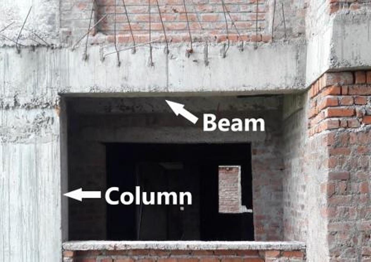
interrelated components. In the case of structural framing, the components include columns, beams, bracing, connections, etc. The richness and variety of structural systems can be appreciated by the available building structural types that range from massive building blocks to shell structures, from structures above or below ground or in water, to structures in outer space. Examples of a few steel-framed structures.


Thnaks to 

Prof. Ajaya Kumar Nayak,


Er.SP.ASWINPALANIAPPAN., M.E.,(Strut/.,)
Structural Engineer