Friday 23 December 2022

COMPONENTS OF THE PEB STRUCTURE

 COMPONENTS OF THE PEB STRUCTURE


  COMPONENTS OF THE PEB STRUCTURE


Pre-Engineered Buildings (PEBs) are the building components that are manufactured at a factory and assembled on-site. Usually, PEBs are steel structures and can be an alternative to conventional structural steel buildings. PEB structural components are fabricated at the factory to the exact size, transported to the site, and assembled at the site, usually with bolted connections. This type of Structural Concept is generally used to build:

ü  Industrial and Small Manufacturing Buildings

ü  Small Retail and Commercial Office Buildings

ü  Warehouses and Storage Units

And Pre-Engineered Buildings (PEBs) are the building components that are mainly classified into two methods they are:

ü  Primary Steel Members

ü  Secondary Steel Members


PRIMARY STEEL MEMBERS:


COLUMN:

ü  It is a vertical structure, used to transfer vertical load. It is a compression member.


RAFTERS:

ü  Rafter is a sloped member. It runs from ridge to hip of the roof.


SECONDARY MEMBERS:

PURLINS:

Beam members carrying roof cladding. Purlins are top mounted on the rafter and transfer load from roof cladding to primary or main members.


LONGITUDINAL BRACING:

Provides lateral stability to the structure and helps transfer the lateral load to ground level. It is also known as diagonal bracing. Usually lies between two vertical columns.


ROOF BRACINGS:

They help to maintain lateral stability of the structure (Prevent shape deformability)


CLADDING:

Cladding will be seated either on purlin or girt. It provides skin resistance and resists lateral load (wind load).


·         ROOF CLADDING

A few proprietary types of cladding may be used in industrial buildings.

ü  Single skin trapezoidal sheeting

ü  Double skin system

ü  Standing seam sheeting

ü  Composite or sandwich panel.

Ø  Flat

Ø  Wide profiled

Ø  Narrow profiled

Ø  Micro-profiled

Ø  Trapezoidal

Ø  Corrugated.


·         WALL CLADDING

ü  Numerous systems exist for the design of external walls for industrial buildings.

ü  Steel sheeting is frequently used due to its high quality.

ü  Sheeting generally supports on side rails.


SAG ROD:

ü  It prevents twisting and lateral bending. It is used to provide alignment of the member. It provides lateral support to purlin.


SIDE RAILS / GIRT:

ü  It is a horizontal structural member providing lateral support to wall cladding and it is also known as a girt.


FLANGE BRACINGS:

ü  It increases the efficiency of the rafter. It connects the rafter & purlin, Column & girt.


 Er. SP. ASWINPALANIAPPAN., M.E., (Strut/.,)., (Ph.D.,)

Structural Engineer

http://civilbaselife.blogspot.com

Thursday 22 December 2022

How to design a sword structure?

 How to design a sword structure?

Uploading: 201915 of 201915 bytes uploaded.

 1. Determine whether the sword structure is suitable for the structure

 Sword structures are generally utilised for high-rise, large-span, complicated frames, heavy cargo or crane lifting, huge vibration, high miserliness conditions, portable, or constantly put together and taken piecemeal structures.

 Structures include endless structures as well as colosseums, pieces houses, islands, television halls, manufactories, storages, garages, and hangars. This fits in with the sword structure’s characteristics.

 2. Structure selection and layout

 Given the variety of factors involved, the layout and selection of the structure should be made with the help of professional masterminds. It's necessary to punctuate “abstract design ” throughout the entire sword structure design process since it's pivotal for the selection and layout of the structure.

 The mechanical relationship between the primary structural system and its subsystems, failure mechanisms, earthquake damage, experimental marvels, and engineering experience can all be used to induce design ideas for issues for which it's delicate to conduct a precise rational analysis. Using a broad perspective, decide the configuration and specific measures of the control structure. Abstract design can help quick and effective early generality, comparison, and selection.

During the selection process, numerous sword structure parameters should be considered. When there's a lot of snow on the roof, the roof curve should encourage snow sliding. Areas with high downfall are given analogous considerations. A support frame will be more cost-effective than one with only connected bumps if the construction is approved. The major factors of a suspense string or string-membrane structure system with wide roof spans can be chosen for structures. Steel-concrete compound structures are constantly used in the design of high-rise sword structures.

 According to the system’s characteristics, cargo distribution, and nature, the structure’s layout should be precisely studied. The mechanical model should be unequivocal, and the stiffness should be invariant. Reduce the influence range of heavy loads or moving loads as much as you can to ensure that they're transmitted to the foundation as snappily as doable. Anti-slide support should be distributed inversely among columns. The centre should be as near to the side force’s action line as possible. However, the structure should be allowed

 about in torsion, If not. There should be several defence lines on the structure’s contrary side.

 On the frame structure’s bottom plan, the cargo transfer direction of the secondary shafts can sometimes be changed to accommodate colourful requirements. The attachment shafts are generally organised in a short path to drop the sampling, but this increases the section of the main ray and lowers the net bottom height, which can sometimes overwhelm the side columns on the top bottom. To conserve the main ray and pillars at this point, the secondary ray can be supported on a shorter main ray.

 3. Structural analysis

Now, direct elastic analysis is generally used in the factual design of sword structures, with p- Δ, and p- δ being considered when the conditions permit. Recent finite element software may take sword’s elastic-plastic parcels and geometric nonlinearity into consideration to some extent. This creates the necessary framework for a more detailed analysis structure.

 Not all structures bear software; typical structures can be discovered in reference books like mechanical primers to get internal forces and distortions without using the software.

 4. Engineering judgment

 The affair result should include “finagled judgment” if the structural software is used rightly. For case, calculating the overall shear force, the period of each direction, the distortion parcels, etc. Decide whether to change the model for new analysis or the computation result grounded on the “engineering decision.” The conditions that apply to colourful software vary. The neophyte should comprehend fully. The computations used in engineering and mechanical computations constantly diverge in specific ways.

 Still, applicable conditions, generalities, and structures will be espoused to ensure the structure’s safety. occasionally hypotheticals with significant crimes will be used to gain practical design styles. The quantitative calculation isn't as pivotal in the design of sword structures as the notion of “applicable conditions, conception, and structure”. masterminds shouldn't overuse the use of structural software. Engineering disasters of this nature can be averted by paying close attention to abstract design and engineering judgment.

 5. element design

 The selection of accoutrements comes first when designing factors. Q235, like an A3, and Q345 are constantly used. To simplify design administration, the primary structure frequently uses a single sword grade. It's also doable to elect a part that's a mix of swords with colourful strengths for fiscal reasons. Q345 can be chosen when the intensity controls the situation. Q235 will be a better option if it's steady. The current proposition uses the elastic-plastic approach to assess the section when designing factors. The flexible approach to structural internal force calculation doesn't match this.

 All of the structural software programs available moment have sampling verification post-processing features. Some software now has the option to move over one position from the handed sampling library for factors that failed the test due to advancements in program technology. And automatically rethink and corroborate the computation till it's successful, like sap2000. One of the purposes of sampling optimisation design is to achieve this. For engineers, it significantly decreases work.

6. Drawing medication

 The design drawing for a sword structure is resolved into two stages the construction detail delineation, and the design drawing company provides the design sketch. According to the design delineation, the sword structure manufacturing establishment generally prepares the construction detail delineation; still, the design company sometimes does so.

 The creation of detailed construction delineations is grounded on design delineations. The delineation and its contents must be finished. To make the process of creating detailed construction delineations that directly reflect the design intent easier, the design delineation should easily express the design base, cargo data, specialized data, design conditions, structural arrangement, element sampling selection, and main knot structure. A list should be used to display the primary accoutrements.

 Detailed construction delineations are frequently known as stakeout delineations or processing delineations. The delineation must be acceptable for direct manufacture and factory processing. A complete list of accoutrements must be attached, and any fresh element units that aren't the same must be drawn and described collectively.


 Er. SP. ASWINPALANIAPPAN., M.E., (Strut/.,)., (Ph.D.,)

Structural Engineer

http://civilbaselife.blogspot.com

Styles of sword structure design

 Styles of sword structure design

 The design of a sword structure can be done in one of three ways simple, nonstop, or semi-continuous. To simplify design computations, joints in structures have been considered to bear as either projected or flexible.

 Simple designs idealise their joints as indefectible legs. Anyhow of the usable moment, nonstop invention presumes that joints are rigid and that connected rudiments cannot rotate relative to one another. maturity of designs created moment calculate on one of these two presuppositions, although a semi-continuous plan, a more practical option, is now doable.

 Following are the styles of design of sword structure

The simple design of the sword structure

 The most conventional system is a simple design, which is still used constantly. Bracing or, in some multi-story structures, concrete cores are generally used to insure a structure’s adaptability to side loads and sway.

 The developer must be apprehensive of the common response presuppositions and make sure that the connections are detailed in a manner that prevents any moments from arising that can negatively impact the structure’s performance.

 The types of details that meet this condition have been demonstrated through numerous times of experience, and the developer should take note of the typical connections on joints in uncomplicated construction.

The nonstop design of sword structures

 Joints that transfer moments between corridors are supposed to be stiff in nonstop design. Frame action is what keeps the frame from swaying.

 The frame analysis is constantly done using the software since the nonstop design is more sophisticated than the introductory design. nonstop frames must be designed with realistic pattern-lading combinations in mind.

 Depending on whether the frame is designed using an elastic or a plastic system, the connections between the members must have differing parcels.

In a flexible design, the joints must have enough rotational stiffness to ensure that the forces and moments distributed throughout the frame do not diverge noticeably from the calculated values.

 The joint needs to be strong enough to support the moments, forces, and shears that affect the frame analysis.

 The strength of the joint, not its stiffness, is the most pivotal factor in plastic design for calculating the maximum cargo capacity. Whether plastic hinges are set up in the joints or the members will depend on how strong the joint is, which will significantly impact how the structure collapses.

 Still, the joint must be specified with enough rigidity to support the preceding reels, If joints are intended to have hinges. When calculating sway stability, sway diversions, and ray diversions, the stiffness of the joints will be pivotal.

Semi-continuous design of sword structure

 True semi-continuous design is more complicated than introductory or nonstop design because the factual common response is more directly represented. The development of logical routines that nearly track the factual connection gusted is extremely labour- ferocious and not suitable for routine design.

 For both armed and unbraced frames, there are two streamlined processes, which are compactly bandied below. Unbraced frames produce side cargo resistance from the bending moments in the columns and shafts, whereas armed frames use a bracing system or a core to induce this resistance.

 Er. SP. ASWINPALANIAPPAN., M.E., (Strut/.,)., (Ph.D.,)

Structural Engineer

http://civilbaselife.blogspot.com
Wednesday 21 December 2022

The characteristics of Sword Structure

 The characteristics of Sword Structure

 Sword is an invariant substance that's strong, plastic, and tough

 Excellent seismic performance, felicity for bearing impact and dynamic loads, and high structural trust ability are all attributes of the sword.

 Sword has a harmonious internal structure that's analogous to that of an isotropic homogeneous body. The fine proposition more nearly matches the sword structure’s factual working performance. The sword structure is, thus, veritably dependable. The rate of viscosity to yield strength is vastly lower than that of concrete and wood. Consequently, given the same stress parameters, the sword structure has a small section, is featherlight, is simple to carry and install, and is applicable for wide spans and high heights.

 The sword structure is heat-resistant but not fire-resistant shielding the structure’s face from temperatures above 150 °C

 Sword loses a substantial quantum of its strength and elastic modulus between the temperatures of 300 and 400 °C, and at about 600 °C, sword strength tends to zero. Refractory accoutrements must shield the sword structure in structures with specific fire safety criteria to increase the fire resistance position.

 • The Steel Structure Has Weak Corrosion Resistance.

It fluently rusts, especially in an atmosphere with high moisture and erosion. generally,     dedusting, galvanizing, painting, and routine conservation are needed for sword structures. To stop erosion, specific preventives like “zinc block anode protection” are demanded by coastal platform structures submerged in seawater.

 The sword structure installation and manufacturing processes are largely mechanized

 Sword structural factors that are snappily produced in manufactories and put together on point. High product effectiveness, quick point assembly, and minimum structure time are all benefits of plant-mechanized, manufacturing of sword structural factors. The most industrialized structure is made of the sword.

 High strength and seismic resistance

Steel structures have advantages over typical corroborated concrete structures, including superior inhomogeneity, high strength, quick construction, good seismic adaptability, and a high recycling rate. The mass of sword members is light under the same stress conditions because the sword has strength and elastic modulus that are several times more advanced than those of masonry and concrete. The sword structure is a flexible damage construction that can identify peril beforehand on and help it due to its substantial prognosticated distortion from the standpoint of being destroyed.

 Er. SP. ASWINPALANIAPPAN., M.E., (Strut/.,)., (Ph.D.,)

Structural Engineer

http://civilbaselife.blogspot.com

7 reasons why sword structure is the stylish choice for domestic construction?

 7 reasons why sword structure is the stylish choice for domestic construction?

 Strength and design freedom

 In terms of colour, texture, and shape, the sword gives engineers a further creative look. Because it combines adaptability, continuity, beauty, delicacy, and plasticity, it offers engineers more inflexibility to trial with generalities and develops new results. Large open fields without intermediate columns or cargo-bearing walls affect by the sword’s long-gauging capacity. It stands out for having the inflexibility to bend to a certain compass, forming segmented angles or free-form combinations for facades, bends, or polls. The sword is less susceptible to on-point variability since it's plant-finished to the tightest conditions beneath well-regulated conditions.

 Fast, effective, and resourceful

In any season, the sword can be assembled presto and effectively. With little on-point labour, factors are-manufactured off- point. Depending on the size of a design, an entire frame can be constructed in days rather than weeks, which results in a 20 to 40 shorter construction period than on-point construction.

 For single homes in further gruelling locales, the sword constantly permits smaller contact points with the land, minimizing the quantum of excavation demanded. A lower, more straightforward foundation is possible due to the structural sword’s lower weight than indispensable architectural accoutrements like concrete. These executional effectiveness advancements restate significant resource edges and fiscal advantages, like quicker design schedules, lower point operation charges, and an earlier return on investment.

 lower than 150 °C causes little change in the sword’s characteristics. In hot workplaces, sword structures are thus applicable, but heat sequestration panels should be used to

 Adaptable and accessible

A structure’s function can alter drastically and snappily moment. A tenant can request variations that vastly raise the bottom cargo. Depending on the requirements and space consumption, walls may need to be moved to produce new interior layouts. Steel construction allows for similar adaptations.

Non-composite sword shafts can be combined with the bottom arbour formerly in place, cover plates can be added to the shafts to boost strength, and shafts and crossbars can fluently be corroborated, supplemented with the further frame, or indeed moved to handle different loads. Communication, computer networking, and electrical wiring may all be fluently penetrated and modified because of sword architecture and bottom systems.

 Endlessly recyclable

 When a sword-framed structure is taken down, its corridor can either be reclaimed or transferred back into the unrestricted-circle recycling system utilized by the sword assiduity. The sword may be reclaimed indefinitely without losing any of its rates. Nothing goes to waste. Because about 30 of moment’s new sword is made from the reclaimed sword, sword reduces the need for natural raw resource use.

 Added fire resistance

 The assiduity now has a solid grasp of how sword structures reply to fire because of the expansive testing of structural steelwork and whole sword structures. ultramodern design and logical styles enable exact specification of fire protection needs for sword-framed structures, constantly leading to significant reductions in the quantum of fire protection demanded.

 Earthquake resistance

 In terms of size, frequency, length of time, and position, earthquakes are unanticipated. Because it's malleable and flexible by nature, the sword is the material of choice for design. Under heavy pressure, it flexes as opposed to breaking or disintegrating. The primary purpose of numerous ray-to-column connections in sword structures is to support graveness loads. They can, still, also repel substantial side loads caused by wind and earthquakes.

It can repel severe winds, earthquakes, hurricanes, and heavy snowfall, among other extreme forces and adverse rainfall conditions. Termites, bugs, mildew, mould, and fungi don't affect them; unlike wood frames, they're also resistant to erosion.

 Lighter and lower environmental impact

 The environmental impact of the construction is lessened by the fact that sword constructions can frequently be mainly lighter than concrete counterparts and need less expansive foundations. The utilization of transportation and energy is dropped because they use smaller and lighter materials. However, sword piling foundations can be removed, o reclaimed, If necessary.

 The sword is energy-effective because heat snappily escapes from sword roofing, keeping homes cool in hotter climates. For better heat retention in cold areas, double-sword panel walls can be adequately isolated.


Er. SP. ASWINPALANIAPPAN., M.E., (Strut/.,)., (Ph.D.,)

Structural Engineer

http://civilbaselife.blogspot.com
What's a sword structure?

 What's a sword structure?

 The term sword structure refers to an essence layout developed with structural sword pieces connected to support loads and give comprehensive stiffness. This construction is dependable and employs smaller raw accoutrements than different forms of structure like concrete and timber structures because of the high adaptability degree of the sword.

The sword is a material that's employed in nearly every kind of structure in a contemporary structure, including field outstations, big artificial manufactories, high-rise constructions, outfit support systems, islands, structures, heavy artificial constructions, and pipe stands.

 sword fabricated with a proper form and chemical composition to satisfy the conditions of a design is understood as a structural sword.

The sword chambers may be available in colourful shapes, heights, and measures, depending on the applicable design specifications. Some may be constructed by hot or cold rolling, while others may be erected by joining flat or fraudulent plates. Some common shapes are Plates, I- shafts, Channels, and Angles.


Er. SP. ASWINPALANIAPPAN., M.E., (Strut/.,)., (Ph.D.,)

Structural Engineer

http://civilbaselife.blogspot.com

Beam Deflection

 Beam Deflection

 In numerous cases of structural and machine designs, members must repel the force applied indirectly or obliquely to their axes. similar members are called shafts. The main members supporting the bottoms of structures are shafts, just as an axle of an auto is a ray. numerous shafts act contemporaneously as torsion members and as shafts. So far it can be said ray is an integral part of the construction.

 Beam Deflection

 Beam deviation means the state of distortion of a ray from its original shape under the work of a force or cargo or weight. One of the most important operations of ray deviation is to gain equations with which we can determine the accurate values of ray diversions in numerous practical cases. diversions are also used in the analysis of statically indeterminate shafts.

 Styles to Determine Beam Deflection

 Several styles are available for determining ray diversions. The principle is the same but differs in fashion and in their immediate ideal.

1.       Direct Integration system

2.      Area Moment Method

3.      Conjugate Beam Method

4.      system of Superposition

 Direct Integration Method

 Beam diversions due to bending are determined from distortion taking place along a span. This is grounded on the thesis that during bending, aeroplane sections through a ray remain plain. For now, it'll be assumed that bending takes place only at about one of the top axes of the sampling. The edge view of the neutral face of a veered ray is called the elastic wind of the ray. The discrimination equation of the elastic wind of a ray

EId2ydx2=MEId2ydx2=M

The product EI is called the flexural rigidity of the beam which is usually constant along the beam.

v = deflections of the elastic curve

θ = dv/dx = v' = slope of the elastic curve

M=EId2vdx2=EIv′′M=EId2vdx2=EIv′′

V=dMdx=ddx(EId2vdx2)=(EIv′′)V=dMdx=ddx(EId2vdx2)=(EIv′′)′

q=dVdx=d2dx2(EId2vdx2)=(EIv′′)′′q=dVdx=d2dx2(EId2vdx2)=(EIv′′)′′

By simplifying-

EId2vdx2=M(x)EId2vdx2=M(x)

EId3vdx3=V(x)EId3vdx3=V(x)

EId4vdx4=q(x)EId4vdx4=q(x)

Here q(x) is the load function. The choice of which equation we will use to determine v depends on the ease with which an expression for moment, shear or load can be formulated.

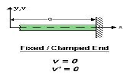
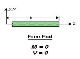
Some Boundary Conditions:

  1. Clamped or fixed support:
     

  2. Roller or pinned support:
    In this case. the end is free to rotate, that’s why the moment is zero.


  1. Free end:


  1. Guided Support:


Er. SP. ASWINPALANIAPPAN., M.E., (Strut/.,)., (Ph.D.,)

Structural Engineer

http://civilbaselife.blogspot.com