The Civil Engineering Industry has a significant role in developing the nation to cater to the need for globalizing market scenarios. In every aspect of infrastructural development, the role and involvement of Civil Engineering experts are inevitable. The knowledge about the process and standards should be known to all. It will be much helpful for anyone, involving in Civil Engineering work at any time reference for their professional knowledge.
Reinforced Concrete Buckling-Restrained Braced Frame with Structural Fuse Detailed for Seismic Loading
Abstract Buckling-restrained braces (BRBs) increase the strength of a system while dissipating a significant amount of hysteretic energy. This research presents a concept for a lateral force-resisting system using a reinforced concrete buckling-restrained braced frame (RCBRB) as a structural fuse for the design of new buildings in seismic regions. Experimental and numerical analysis results are presented for a single-story subassembly. The experiment was performed on a reduced-scale prototype reinforced concrete (RC) frame designed and constructed with modern seismic details and supplemented with a BRB as a structural fuse to examine the structural performance of the RCBRB frame under quasi-static cyclic loads. The BRB fractured in tension at approximately 3.5% drift ratio with minor repairable damage observed in the RC frame members. A numerical analysis model was developed in OpenSees with various material types and elements to model the nonlinear behaviour of the proposed system compared with the numerical analysis model of the undamaged RC frame; the global and local experimental response of the RC frame and BRB was used to validate the numerical model. When compared to the numerical analysis results of the RC frame, the resulting RCBRB frame increased both the lateral load capacity and stiffness of the RC frame by approximately 250%. The resulting lateral force-resisting system would be capable of resisting strong earthquake ground motions that can yield or even fracture the BRB without damaging the RC frame beyond a state of repair. The BRB was attached to the RC frame utilizing steel embed plates cast into the concrete that were designed using the uniform force method. A numerical model was developed and validated using the experimental results and showed that the RCBRB frame more than doubled the lateral strength and nearly tripled the total hysteretic energy dissipation when compared to the numerical analysis model results of an undamaged RC frame alone. Thanks too Authors: Jake D. Dunn, S.M.ASCEjacobddunn@gmail.com, and Chris P. Pantelides, F.ASCEhttps://lnkd.in/gbHuzmNsc.pantelides@utah.edu AUTHOR AFFILIATIONS Publication: Journal of Structural Engineering Volume 151, Issue 2 https://lnkd.in/gfpxKKpb
Revisiting the Ambient and Postfire Strength of Channel-Type Shear Connectors
Abstract
The ability of steel-concrete composite floor systems to withstand loads relies on shear connectors, which prevent or limit slip between the two materials. This paper presents an experimentally validated numerical investigation along with parametric studies aimed at evaluating the behaviour of channel-type shear connectors in ambient and postfire conditions. A three-dimensional finite-element model of a push-out test was developed, which incorporated the nonlinear material properties of steel and concrete in ambient conditions as well as their thermomechanical properties to simulate heating and cooling and the effects of fire exposure. The model was validated using experimental data obtained by the authors and those from previous studies. Subsequently, a parametric study assessed the load-slip behaviour of the channel-type connectors assuming different compressive strengths of concrete, slab thicknesses, connector dimensions, and maximum temperatures experienced. The failure mode in ambient and postfire conditions was observed to be affected by the length, web thickness, and height of the channel, but not by its flange thickness. The numerical results, combined with an analytical investigation of failure mechanisms, were then used to develop an improved design equation for channel-type shear connectors, which performs noticeably better than current design provisions in comparison with experimental data.
Virtual Constant Load Method for Moving Force Identification on Simply Supported Beam
Abstract During the operation of a simply supported beam bridge, moving forces are a primary load on the bridge. Therefore, moving force identification (MFI) is essential for ensuring bridge safety. Nevertheless, current theories for identifying moving forces present shortcomings. To ascertain the force through the bridge beam response, it is essential to know the beam’s bending stiffness. Practical or laboratory measurements of this bending stiffness are difficult to record, limiting practical implementations of MFI theory. Therefore, a virtual constant load (VCL) method is developed to achieve MFI when the beam bending stiffness is unknown. The proposed method uses a vehicle with a known axle load to efficiently traverse a simply supported beam. Upon establishing a correlation between the dynamic responses and the MFI model under the influence of the known axle load, a correction coefficient is derived for characterizing the strain response of the MFI model. This coefficient includes bending stiffness information, eliminating the need to explicitly solve for the beam bending stiffness. The updated model effectively achieves force identification when the bridge bending stiffness is unknown. To validate this method, MFI was conducted using numerical and laboratory analyses. The results demonstrate that the proposed method can accurately identify moving forces acting on beams with unknown bending stiffness. THANKS TO Authors: Hai-Chao Zhouzhouhc1712@163.com, Hong-Nan Li, F.ASCEhnli@dlut.edu.cn, Ting-Hua Yi, M.ASCEyth@dlut.edu.cn, and Dong-Hui Yang, M.ASCEdhyang@dlut.edu.cn AUTHOR AFFILIATIONS Publication: Journal of Structural Engineering Volume 151, Issue 2 https://lnkd.in/gAcVWFYM
Isolated footing design as per IS 456-2000 code | structural design | civil engineering
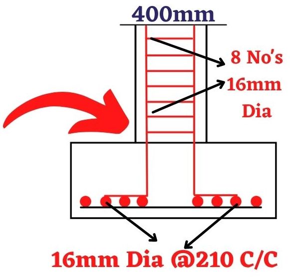
Footing the structure which exists below the ground level; the strength of the building is depending upon the reinforcement details of the foundation. The reinforcement details depend upon the total load which is acts on building structures. The loads related to the gravity loads and gravity loads are considered in the foundation design. The load is taken as a point load which acts in the column section. In this article, I will explain to you the clear concept regarding the isolated footing design as per IS 456-2000 code by manual calculations. In the column design and assume the load is taken as 1200kN and dimensions of the columns are obtained as 400mmX400mm cross-section.
Basic formulas used in the design as per IS456-2000 code
For the design of RCC footing as per the IS456 code the following 8 basic formulas are used which are given as per IS 456 standards.
Area of footing = Total load/SBC
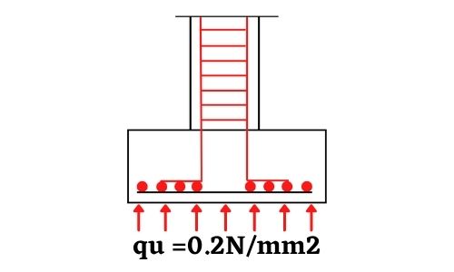
Soil pressure = qu = Total load/Area of footing
Factored shear force Vu1 = (quB/2) (B-C1-2d)
One way shear resistance = Vc1 = τcbd
Factored shear force / Two way shear = Vu2 = qu (B2-(C1+d)2)
Steps used in Isolated footing design as per IS 456 code
The following six steps are used in the isolated footing design as per IS 456
Load calculations
Size of footings
Calculation of net upward pressure at ultimate load
Calculation of one-way shear to determine the depth
Check for punching shear / Two-way shear
Reinforcement design
Example of Isolated footing design as per IS 456-2000 code standards
Design RCC isolated footing for 400 mmX400 mm column size which carries a load of 1200kN on the column, take Soil bearing capacity of the soil (SBC) is 200kN/m2. Assume M20 grade concrete and Fe 415 grade steel.
Consider self-weight of footing and backfill is 10% column load
= (10%column load) = (10/100)1800 = 120kN
Now the total load on the column = Factor load + 10% column load
= 1800+120 =1920 kN
Step 2: Size of footings calculations
As per step1, the total load is obtained as 1920 kN
Let us consider the square footing which is having length and width as B
So the area of footing is given by BXB = B2
As per the formula of area of footing is given by
B2 = Total load/SBC = 1920/200 = 9.6 m2
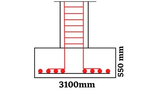
By solving we can get the value of B = 3.1m
So final area of footing provided is = 3.1mX3.1m =9.61 m2
Step 3: Calculation of net upward pressure at ultimate load
The calculated ultimate load from step 1 is 1920kN
Soil pressure = qu = Total load/Area of footing = 1920/9.61 = 199.80 kN/m2
So take soil pressure qu = 200 kN/m2
Upward pressure
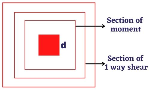
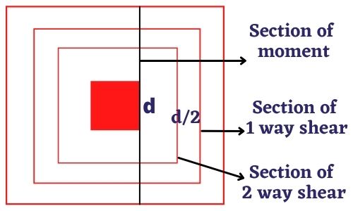
Step 4: Calculation and check for one way shear to determine the depth
One way shear and moment
From formulae of factored shear force for one-way shear
Factored shear force Vu1 = (quB/2) (B-C1-2d)
By taking the values Vu1 = ((0.2X3100)/2)(3100-400-2d)
By solving the above equation we can get
Vu1 = 310(2700-2d) ————————– equation 1
By assuming the percentage of steel in the footing
Pt =0.15%
From table 19 of IS 456-2000 code
Design shear = 0.36 N/mm2
And one way shear resistance is given by Vc1 = τcbd
By substituting the values Vc1 = 0.36X3100d
Vc1 =1116d ——————————- equation 2
By solving equation 1 and equation 2
310(2700-2d) = 1116d
We can get the value of d as 482.19mm
Let us consider the cover as 68mm
So overall depth is given by 482+68 = 550mm
Depth of isolated footing
Step 5: Check for punching shear / Two-way shear
Since we have formulae
Factored shear force / Two way shear = Vu2 = qu (B2-(C1+d)2)
Two-way shear and moment
By substituting the values in the above expression
Vu2 = 0.2 (31002 – (400+550)2)
= 1741.5 kN
Again we have punching / two-way shear resistance
Vc2 = Ksb0d
Where b0 = 4(C1+d)
= 4(400+550)
= 3800
From clause 31.6.3 permissible shear stress ( IS 456-2000)
c = 0.25 fy1/2 = 0.25X201/2 = 1.118 N/mm2 and Ks =1
By substituting the values we can get
Vc2 = 1X1.118X3800X550
= 2336.62 kN
So here Vc2 > Vu2, hence 550mm depth is safe
Step 6: Reinforcement design calculation
We have the ultimate moment expression from the formulae section
Mu = (quB/8) (B-C)2
By substituting the values we can get
Mu = ((0.2X3100)/8) (3100-400)2
Mu = 564.975 kN.m
By using the Mu expression we can easily calculate the Ast value
Mu = 0.87fyAstd(1-(Astfy/bdfck))
564.975 X 106 = 0.87X20XAstX550 (1-(AstX415/3100X400X20))
By solving the above equation we can get the value of Ast
So here Ast = 2951.4 mm2
Let us consider 16mm diameter bars
Area of 1 bar provided = µ/4(16)2 = 201 mm2
Number of bars required = Ast/Area of 1 bar = 2951.4/201 = 14.68no’s
Take 15 numbers of 16 mm diameter bars
Spacing = (A/Ast)XB
= (201/2951.4)X3100
= 211.12 mm
So the final reinforcement for isolated footing as per IS 456-2000 code is obtained by using 16mm diameter bars at 210 C/C distance in both X direction and Y direction.
The final reinforcement view is shown in the below figure.
Final reinforcement details
Conclusion of complete isolated footing design as per IS 456-2000 code
Well, now the above-explained concepts are related to the complete design of isolated footing as per IS 456-2000 code. The detailed calculation is shown for a 1200kN load with a column size of 400mmX400mm dimensions. As per the final detailing the reinforcement details are obtained by using 16mm diameter bars at 210 C/C distance in both the X direction and Y direction.